Description
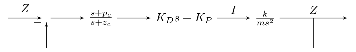
This is a complete LaTeX document with a document class of standalone. It includes the packages amsmath, amsthm, and tikz. The tikz package is used to draw a block diagram of a control system. The diagram is drawn using the tikzpicture environment within a standalone documentclass. The different elements of the control system are represented by nodes of different shapes and styles, such as input, sum, controller, block, and output, and are positioned using the positioning library. The arrows between the nodes represent the flow of signals between them and are specified using the draw command with the -> option to indicate the direction of the arrow. The text labels for the arrows are specified using the node command with appropriate positioning options. The diagram also includes some mathematical expressions specified in the node text using $ delimiters.
Keywords
tikz, standalone, amsmath, amsthm, positioning, shapes, arrows, input, sum, controller, block, output.
Source Code
\documentclass{standalone}
\usepackage{amsmath, amsthm}
\usepackage{tikz}
\usetikzlibrary{positioning}
\usetikzlibrary{shapes,arrows}

\begin{document}
\begin{tikzpicture}[auto, >=latex']
    % Nodes
    \node [input] (input) {};
    \node [sum, right = 1cm of input] (sum) {};
    \node [controller, right = 1cm of sum] (con1) {$\frac{s+p_c}{s+z_c}$};
    \node [controller, right = 1cm of con1] (con2) {$K_D s + K_P$};
    \node [block, right = 1cm of con2] (system2) {$\frac{k}{ms^2}$};
    \node [output, right = 2cm of system2] (output) {};
    \node [input, below = 0.5cm of con2] (m) {};
    % Arrows
    \draw [draw,->] (input) -- node {$Z_\re$} (sum);
    \draw [->] (sum) -- (con1);
    \draw [->] (con1) -- (con2);
    \draw [->] (con2) -- node {$I$} (system2);
    \draw [->] (system2) -- node (y) {$Z$}(output);
    \draw [-] (y) |- (m) {} ;
    \draw [->] (m) -| node[pos=0.99] {$-$}  node [near end] {} (sum);
    \end{tikzpicture}
\end{document}