Description
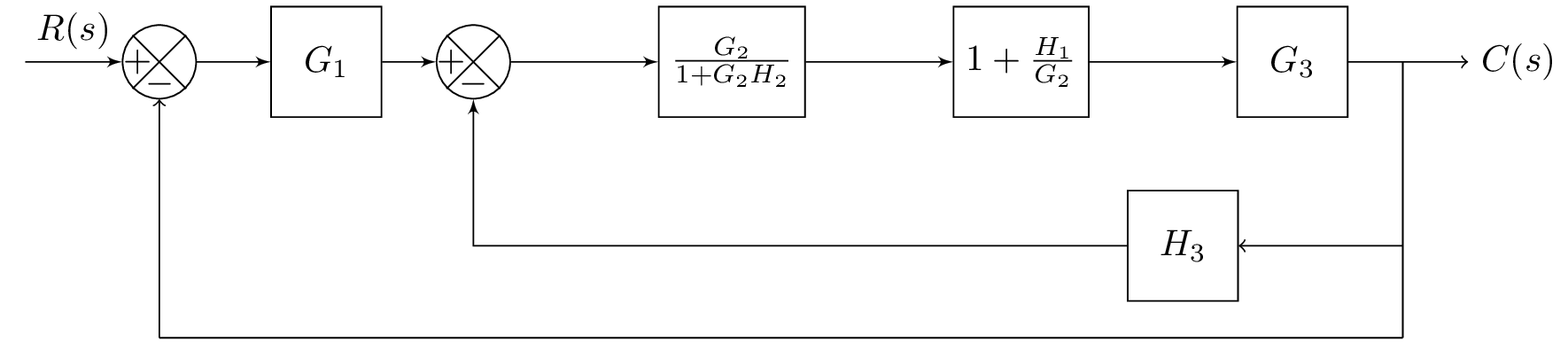
The code above is a LaTeX document that generates a block diagram using the TikZ package. It defines a series of blocks and components, including input, adders, and feedback loops, and connects them using arrows and lines. The diagram represents a system with multiple blocks labeled as , , , and , and a feedback loop with a block labeled as . The diagram also includes labels and annotations for the various components and connections, such as for the input and for the output. The code also defines some custom styles and commands for drawing the blocks and connecting them in a visually pleasing manner.
Keywords
standalone, blox, tikz, positioning, equal, intersections, tkz-euclide, connect, let, veclen, atan2, insert path, bXInput, bXComp, bXLink, bXBloc, bXChain, bXBranchx, bXBranchy, draw, node, right, center, path, name, intersections, of.
Source Code
\documentclass{standalone}

\usepackage{blox}
\usepackage{tikz}
\usetikzlibrary{positioning}
\newcommand{\equal}{=}
\usepackage{tikz}
\usetikzlibrary{intersections}
\usepackage{tkz-euclide}
% Radius for arc over intersection
\def\radius{1.mm}

\tikzset{
	connect/.style args={(#1) to (#2) over (#3) by #4}{
		insert path={
			let \p1=($(#1)-(#3)$), \n1={veclen(\x1,\y1)},
			\n2={atan2(\y1,\x1)}, \n3={abs(#4)}, \n4={#4>0 ?180:-180}  in
			(#1) -- ($(#1)!\n1-\n3!(#3)$)
			arc (\n2:\n2+\n4:\n3) -- (#2)
		}
	},
}

\begin{document}
\begin{tikzpicture}
\bXInput{A}				% Input
\bXComp{B}{A}			% First adder
\bXLink[$R(s)$]{A}{B}	% Input Label
\bXBloc[2]{C}{$G_1$}{B}	% Block G1
\bXLink{B}{C}			% First added -- G1
\bXComp{D}{C}			% Second adder
\bXChain[4]{D}%
	{G2Feed/$\frac{G_2}{1+G_2H_2}$,H1G2unity/$1+\frac{H_1}{G_2}$,G3/$G_3$}

\bXLink{C}{D}
%\bXLink{E}{G2}
%\bXLink{G2}{adder4}		% G2 to adder

%\bXBloc[3]{G3Block}{$G_3$}{adder4} % G3
%\bXBranchy[7.5]{BranEnd}{H3BlockRight} % Right H3 Block
%\bXBranchy[2.5]{H3BlockRight}{BranEndReturn} % Right H3 Block

\bXBranchx[3]{G3}{BranEnd} % branch before output
\bXBranchy[5]{BranEnd}{H3BlockRight} %H3BlockRight

\bXBloc[-7.5]{H3Block}{$H_3$}{H3BlockRight}	% H3 Block
\bXBranchy[2.5]{H3BlockRight}{returnToInputRight}
\bXBranchy[7.5]{B}{adder1Down}
\draw[-] (BranEnd.center) -- (H3BlockRight.center);
\draw[->] (H3BlockRight.center) -- (H3Block);


\node[right = 0.5cm of BranEnd] (end) {$C(s)$};
\draw[->] (G3) -- (end);

%H3 to second adder
\bXLinkxy{H3Block}{D}
%Output back to input, feedback loop
\draw[-] (H3BlockRight.center) -- (returnToInputRight.center);
\draw[-] (returnToInputRight.center) -- (adder1Down.center);
\draw[->] (adder1Down.center)  -- (B);
%\draw[-] (H3Block) -- (adder3down.center);
%\path[name path=line] (adder3down.center) -- (E);
%\path[name intersections={of=H2 to adder2down and line,by=inter}];
%\draw[->,connect=(adder3down.center) to (E) over (inter) by 3pt ];

%\bXLinkxy{BranEndReturn}{B}
 %\bXLinkyx{Bran2}{H2Block}
\end{tikzpicture}
\end{document}