Description
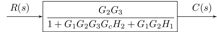
The code above produces a block diagram in LaTeX using the blox and tikz packages. The block diagram consists of three blocks: an input block labeled "A", a transfer function block labeled "C" with the transfer function , and an output block labeled "E". There are also two arrows with labels connecting the input block to the transfer function block and the transfer function block to the output block. The first arrow is labeled with "", and the second arrow is labeled with "".
Keywords
amsmath, amssymb, blox, tikz, tikzpicture, bXInput, bXBloc, bXOutput, bXLink.
Source Code
\documentclass{standalone}
\usepackage{amsmath}  % For math
\usepackage{amssymb}  % For more math

\usepackage{blox}
\usepackage{tikz}
\begin{document}
\begin{tikzpicture}
\bXInput{A}
\bXBloc[4]{C}{$\cfrac{G_2G_3}{1+G_1G_2G_3G_cH_2+G_1G_2H_1}$}{A}
\bXOutput[4]{E}{C}
\bXLink[$R(s) \quad $]{A}{C}
\bXLink[$\quad C(s)$]{C}{E}
\end{tikzpicture}

\end{document}