Description
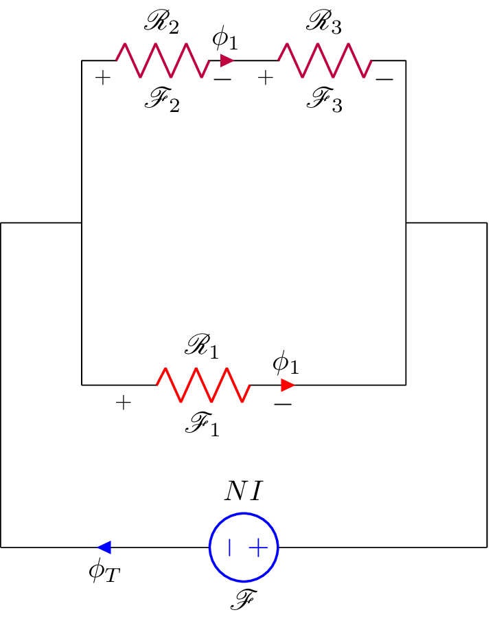
The code is a LaTeX document that generates an electrical circuit diagram using the circuitikz package. The circuit diagram consists of a voltage source, three resistors, and wires connecting them. The resistors are labeled with symbols in the mathrsfs font, and the arrows indicating the direction of the current are labeled with symbols in math mode. The circuit elements are colored in blue, purple, and red. The document also includes packages for graphics and math symbols and defines a new command for the equals sign. The document is set up to be compiled as a standalone file. The resulting image has no border and can be used as a standalone figure.
Keywords
circuitikz, graphicx, mathrsfs, amssymb, amsmath, circuit, circuit diagram, circuit components, electric circuit, electric circuit diagram, resistor, voltage source, current source, switch, node, path, coordinates, labels, arrows, colors.
Source Code
\documentclass{standalone}
\usepackage[american]{circuitikz}
\usepackage{graphicx}
\usepackage{mathrsfs}
\usepackage{latexsym,amssymb,amsmath}
\newcommand{\equal}{=}
\begin{document}
	\begin{circuitikz}
		\draw (6,0) to [V,i^>=$\phi_T$, l^= $\mathscr{F}$,v_>=$NI$, color=blue] (0,0)
		(0,0) -- (0,4)
		(0,4) -- (1,4)
		(1,4) -- (1,2)
		(1,4) -- (1,6)
		(1,6) to [R,i>=$\phi_1$, l^= $\mathscr{R}_{2}$,v_>=$\mathscr{F}_2$, color=purple] (3,6)
		(3,6) to [R, l^= $\mathscr{R}_{3}$,v_>=$\mathscr{F}_3$, color=purple] (5,6)
		(5,6) -- (5,4)
		(1,2) to [R,i>=$\phi_1$, l^= $\mathscr{R}_{1}$,v_>=$\mathscr{F}_1$, color=red] (4,2)
		(4,2) -- (5,2)
		(5,2) -- (5,4)
		(5,4) -- (6,4)
		(6,4) -- (6,0)
		;\end{circuitikz}
	\label{fig:q1fig}
\end{document}