Description
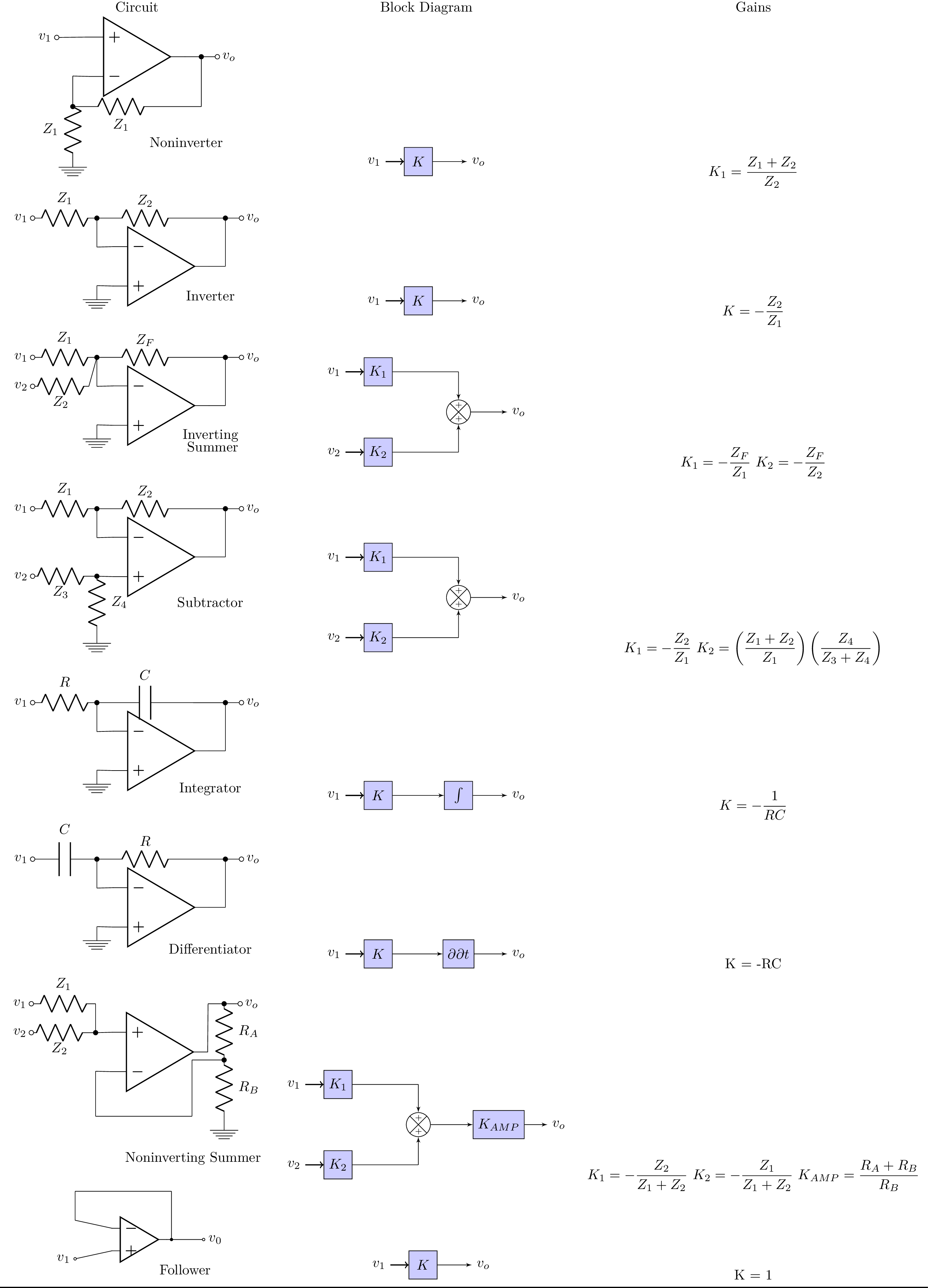
The code is a LaTeX document that creates a table with three columns. The first column contains circuit diagrams created using the circuitikz package, which is used for drawing electrical circuits. The second column contains block diagrams created using the tikz package, which is a powerful package for creating graphics and diagrams. The third column contains the gain equations for each circuit.
The first circuit in the table is a non-inverting op-amp amplifier circuit, which takes an input voltage and amplifies it to produce an output voltage . The gain of this circuit is given by the equation .
The second circuit in the table is an inverting op-amp amplifier circuit, which also takes an input voltage and amplifies it to produce an output voltage , but with an inverted polarity. The gain of this circuit is given by the equation .
The third circuit in the table is a summing op-amp amplifier circuit, which takes multiple input voltages , , and , and sums them to produce an output voltage . The gain of this circuit is given by the equation , where is the feedback resistor and , , and are the input resistors.
Keywords
tikzpicture, node, draw, rectangle, fill, text, above, left, right, below, circle.
Source Code
% Copied this table from the textbook
\documentclass{standalone}
\usepackage{graphicx} % Required for inserting images
\usepackage{tikz}
\usetikzlibrary{positioning}
\usetikzlibrary{shapes,arrows}
\newcommand{\sse}{\mathrm{ss}}
\newcommand{\re}{\mathrm{ref}}
\usepackage{amsmath, amsthm}
\usepackage{booktabs}
\usepackage{tabularx}
\usepackage{circuitikz}

\usetikzlibrary{decorations.text}
\tikzset{add/.style n args={4}{
		minimum width=6mm,
		path picture={
			\draw[black]
			(path picture bounding box.south east) -- (path picture bounding box.north west)
			(path picture bounding box.south west) -- (path picture bounding box.north east);
			\node at ($(path picture bounding box.south)+(0,0.13)$)     {\tiny #1};
			\node at ($(path picture bounding box.west)+(0.13,0)$)      {\tiny #2};
			\node at ($(path picture bounding box.north)+(0,-0.13)$)        {\tiny #3};
			\node at ($(path picture bounding box.east)+(-0.13,0)$)     {\tiny #4};
		}
	}
}

\begin{document}
	\begin{tabular}{c c c}
%		\toprule

		Circuit & Block Diagram & Gains \\

		 \begin{circuitikz}[american voltages,scale =0.8] \draw
		 	(0,0) node[op amp,xscale=1,yscale=-1] (amp) {}
	(amp.out) to[short] (2,0) node[right](target) {}
	(2,0) to [short,*-] (2, -1.55)
	(-2,-1.55) to [R, l_= $Z_1$] (1,-1.55) -- (1,-1.55)
	(1,-1.55) to [short] (2, -1.55)
	(2,0) to [short, -o] (2.5,0) node[right](end){$v_o$}
	(amp.+) to [short, -o] (-2.5,0.6)node[left](){$v_1$}
	(amp.-) to [short] (-2,-0.6)
	(-2,-0.6) to [short, -*] (-2,-1.55)
	 (-2,-1.55) to [R, l_= $Z_1$] (-2,-3) node[ground]{}
		node[below of = target,label={[align=right]Noninverter}, xshift= -0.5cm, yshift = -1.5cm]{};
		 	;\end{circuitikz} &

		 \begin{tikzpicture}[node distance=1.5cm,auto,>=latex']
		 \tikzstyle{int}=[draw, fill=blue!20, minimum size=2em]
		 \tikzstyle{init} = [pin edge={to-,thick,black}]
		 \node [int, pin={[init]left:$v_1$}] (a) {$K$};
		 \node (end) [right of=a, node distance=1.5cm]{$v_o$};
		 \draw[->] (a) -- (end) ;
		 %\draw[->] (c) edge node {$p$} (end) ;
		 \end{tikzpicture}  &
		  $ K_1 = \dfrac{Z_1+Z_2}{Z_2} $
		  \\
\begin{circuitikz}[american voltages,scale =0.8] \draw (0,0) node[op amp](amp9){}
	(amp9.out) to[short] (2,0) node[right](target) {}
	(2,1.5)  to[short,*-] (2,0)
	(2,1.5) to [short, -o] (2.5,1.5) node[right](end){$v_o$}
	(-2,1.5) to [R, l^= $Z_2$] (1,1.5) -- (1,1.5)
	(1,1.5) -- (2,1.5)
	(-2,1.5)to[short, *-](-2,0.60)
	(-2,0.60)to[short](amp9.-)
	(amp9.+) to[short] (-2,-0.6)
	(-2,1.5) to [R, l_= $Z_1$,-o] (-4,1.5) -- (-4,1.5) node[left](v1){$v_1$}
	(-2,-0.6) node[ground]{}
	node[below of = target,label={[align=right]Inverter}, xshift= -0.5cm, yshift = -0.1cm]{};
\end{circuitikz}
&

\begin{tikzpicture}[node distance=1.5cm,auto,>=latex']
\tikzstyle{int}=[draw, fill=blue!20, minimum size=2em]
\tikzstyle{init} = [pin edge={to-,thick,black}]
\node [int, pin={[init]left:$v_1$}] (a) {$K$};
\node (end) [right of=a, node distance=1.5cm]{$v_o$};
\draw[->] (a) -- (end) ;
%\draw[->] (c) edge node {$p$} (end) ;
\end{tikzpicture}
&

$ K = -\dfrac{Z_2}{Z_1} $
\\

\begin{circuitikz}[american voltages,scale =0.8] \draw (0,0) node[op amp](amp8){}
	(amp8.out) to[short] (2,0) node[right](target) {}
	(2,1.5)  to[short,*-] (2,0)
	(2,1.5) to [short, -o] (2.5,1.5) node[right](end){$v_o$}
	(-2,1.5) to [R, l^= $Z_F$] (1,1.5) -- (1,1.5)
	(1,1.5) -- (2,1.5)
	(-2,1.5)to[short, *-](-2,0.60)
	(-2,0.60)to[short](amp8.-)
	(amp8.+) to[short] (-2,-0.6)
	(-2,1.5) to [R, l_= $Z_1$,-o] (-4,1.5) -- (-4,1.5) node[left](v1){$v_1$}
	(-2.25,0.6) to [R, l^= $Z_2$,-o] (-4,0.6) -- (-4,0.6) node[left](v2){$v_2$}
		(-2.25,0.6) -- (-2,1.5)
	(-2,-0.6) node[ground]{}
	node[below of = target,label={[align=right]Inverting\\Summer}, xshift= -0.5cm, yshift = -0.4cm]{};
\end{circuitikz}
&

\begin{tikzpicture}[node distance=2cm,auto,>=latex']
	\tikzstyle{int}=[draw, fill=blue!20, minimum size=2em]
	\tikzstyle{init} = [pin edge={to-,thick,black}]
	(0,0) \node [int, pin={[init]left:$v_1$}] (a) {$K_1$};
	\node [int, pin={[init]left:$v_2$},below of=a] (b) {$K_2$};
	\node[draw,circle,add={+}{}{+}{},right of =a, yshift=-1cm](mixer){};
	\node (end) [right of=mixer, node distance=1.5cm]{$v_o$};
	\node [coordinate,right of =a](a2){};
	\node [coordinate,right of =b](b2){};
	%\node (end) [right of=a, node distance=1.5cm]{$v_o$};
	\draw[->] (mixer) -- (end) ;
	\draw[-] (a) -- (a2) ;
	\draw[-] (b) -- (b2) ;
	\draw[->] (a2) -- (mixer) ;
	\draw[->] (b2) -- (mixer) ;
\end{tikzpicture}
&

$ K_1 = -\dfrac{Z_F}{Z_1} $
$	K_2 = -\dfrac{Z_F}{Z_2} $


 \\

 \begin{circuitikz}[american voltages,scale =0.8] \draw (0,0) node[op amp](amp7){}
 	(amp7.out) to[short] (2,0) node[right](target) {}
 	(2,1.5)  to[short,*-] (2,0)
 	(2,1.5) to [short, -o] (2.5,1.5) node[right](end){$v_o$}
 	(-2,1.5) to [R, l^= $Z_2$] (1,1.5) -- (1,1.5)
 	(1,1.5) -- (2,1.5)
 	(-2,1.5)to[short, *-](-2,0.60)
 	(-2,0.60)to[short](amp7.-)
 	(amp7.+) to[short] (-2,-0.6)
 	(-2,1.5) to [R, l_= $Z_1$,-o] (-4,1.5) -- (-4,1.5) node[left](v1){$v_1$}
 	(-2.25,-0.6) to [R, l^= $Z_3$,-o] (-4,-0.6) -- (-4,-0.6) node[left](v2){$v_2$}
 	(-2.25,-0.6) -- (-2,-0.6)
 	(-2,-0.6) to [R, l^= $Z_4$,*-] (-2, -2.25)node[ground]{}
 	node[below of = target,label={[align=right]Subtractor}, xshift= -0.5cm, yshift = -0.5cm]{};
 \end{circuitikz}
 &

 \begin{tikzpicture}[node distance=2cm,auto,>=latex']
 \tikzstyle{int}=[draw, fill=blue!20, minimum size=2em]
 \tikzstyle{init} = [pin edge={to-,thick,black}]
 (0,0) \node [int, pin={[init]left:$v_1$}] (a) {$K_1$};
 \node [int, pin={[init]left:$v_2$},below of=a] (b) {$K_2$};
 \node[draw,circle,add={+}{}{+}{},right of =a, yshift=-1cm](mixer){};
 \node (end) [right of=mixer, node distance=1.5cm]{$v_o$};
 \node [coordinate,right of =a](a2){};
 \node [coordinate,right of =b](b2){};
 %\node (end) [right of=a, node distance=1.5cm]{$v_o$};
 \draw[->] (mixer) -- (end) ;
 \draw[-] (a) -- (a2) ;
 \draw[-] (b) -- (b2) ;
 \draw[->] (a2) -- (mixer) ;
 \draw[->] (b2) -- (mixer) ;
 \end{tikzpicture}
 &

 $ K_1 = -\dfrac{Z_2}{Z_1} $
 $	K_2 = \left(\dfrac{Z_1+Z_2}{Z_1} \right) \left(\dfrac{Z_4}{Z_3+Z_4} \right)$

 \\

  \begin{circuitikz}[american voltages,scale =0.8] \draw (0,0) node[op amp](amp5){}
  	(amp5.out) to[short] (2,0) node[right](target) {}
  	(2,1.5)  to[short,*-] (2,0)
  	(2,1.5) to [short, -o] (2.5,1.5) node[right](end){$v_o$}
  	(-2,1.5) to [C, l^= $C$] (1,1.5) -- (1,1.5)
  	(1,1.5) -- (2,1.5)
  	(-2,1.5)to[short, *-](-2,0.60)
  	(-2,0.60)to[short](amp5.-)
  	(amp5.+) to[short] (-2,-0.6)
  	(-2,1.5) to [R, l_= $R$,-o] (-4,1.5) -- (-4,1.5) node[left](v1){$v_1$}
  	(-2,-0.6) node[ground]{}
  	node[below of = target,label={[align=right]Integrator}, xshift= -0.5cm, yshift = -0.35cm]{};
  \end{circuitikz}
  &

  \begin{tikzpicture}[node distance=2cm,auto,>=latex']
  \tikzstyle{int}=[draw, fill=blue!20, minimum size=2em]
  \tikzstyle{init} = [pin edge={to-,thick,black}]
  (0,0) \node [int, pin={[init]left:$v_1$}] (a2) {$K$};
  \node [int,right of=a2] (b2) {$\int$};
  \draw [->] (a2) to (b2);
  \node(end2) [right of=b2, node distance=1.5cm] {$v_o$};
  \draw [->] (b2) to (end2);

%  \draw[->]b2 -- end2;
  \end{tikzpicture}
  &

  $ K = -\dfrac{1}{RC} $
  \\

  \begin{circuitikz}[american voltages,scale =0.8] \draw (0,0) node[op amp](amp4){}
  	(amp4.out) to[short] (2,0) node[right](target) {}
  	(2,1.5)  to[short,*-] (2,0)
  	(2,1.5) to [short, -o] (2.5,1.5) node[right](end){$v_o$}
  	(-2,1.5) to [R, l^= $R$] (1,1.5) -- (1,1.5)
  	(1,1.5) -- (2,1.5)
  	(-2,1.5)to[short, *-](-2,0.60)
  	(-2,0.60)to[short](amp4.-)
  	(amp4.+) to[short] (-2,-0.6)
  	(-2,1.5) to [C, l_= $C$,-o] (-4,1.5) -- (-4,1.5) node[left](v1){$v_1$}
  	(-2,-0.6) node[ground]{}
  	node[below of = target,label={[align=right]Differentiator}, xshift= -0.5cm, yshift = -0.4cm]{};
  \end{circuitikz}
  &

  \begin{tikzpicture}[node distance=2cm,auto,>=latex']
  \tikzstyle{int}=[draw, fill=blue!20, minimum size=2em]
  \tikzstyle{init} = [pin edge={to-,thick,black}]
  (0,0) \node [int, pin={[init]left:$v_1$}] (a2) {$K$};
  \node [int,right of=a2] (b2) {${\partial}{ \partial t}$};
  \draw [->] (a2) to (b2);
  \node(end2) [right of=b2, node distance=1.5cm] {$v_o$};
  \draw [->] (b2) to (end2);

  %  \draw[->]b2 -- end2;
  \end{tikzpicture}
  &

  $$ K = -RC $$
   \\

   \begin{circuitikz}[american voltages,scale =0.8] \draw (0,0) node[op amp,yscale=-1](amp2){}
   	(amp2.out) to[short] (1.5,1.5) node[right](target) {}
   	(2,1.5)  to[short,*-] (1.5,1.5)
   	(2,1.5) to [short, -o] (2.5,1.5) node[right](end){$v_o$}
   	(-2,1.5)to[short, -*](-2,0.60)
   	(-2,-0.60)to[short](amp2.-)
   	(amp2.+) to[short] (-2,0.6)
   	(-2,1.5) to [R, l_= $Z_1$,-o] (-4,1.5) -- (-4,1.5) node[left](v1){$v_1$}
   	(-2.25,0.6) to [R, l^= $Z_2$,-o] (-4,0.6) -- (-4,0.6) node[left](v2){$v_2$}
   	(2,1.5) to [R, l^= $R_A$,-*] (2,-0.25) -- (2,-0.25)
   	(2,-0.25) to [R, l^= $R_B$] (2,-2) -- (2,-2)
   	(-2.25,0.6) -- (-2,0.6)
   	(-2,-0.6) -- (-2,-2)
   	(-2,-2)	-- (1,-2)
   	(1,-2) -- (1, -0.25)
   	(1, -0.25) -- (2, -0.25)
   	(2,-2) node[ground]{}
   	node[below of = target,label={[align=right]Noninverting Summer}, xshift= -0.5cm, yshift = -3.25cm]{};
   \end{circuitikz}
   &

   \begin{tikzpicture}[node distance=2cm,auto,>=latex']
   \tikzstyle{int}=[draw, fill=blue!20, minimum size=2em]
   \tikzstyle{init} = [pin edge={to-,thick,black}]
   (0,0) \node [int, pin={[init]left:$v_1$}] (a) {$K_1$};
   \node [int, pin={[init]left:$v_2$},below of=a] (b) {$K_2$};
   \node [int,right of=mixer] (c) {$K_{AMP}$};
   \node[draw,circle,add={+}{}{+}{},right of =a, yshift=-1cm](mixer){};
   \node (end) [right of=c, node distance=1.5cm]{$v_o$};
   \node [coordinate,right of =a](a2){};
   \node [coordinate,right of =b](b2){};
   %\node (end) [right of=a, node distance=1.5cm]{$v_o$};
   \draw[->] (mixer) -- (c) ;
   \draw[->] (c) -- (end) ;
   \draw[-] (a) -- (a2) ;
   \draw[-] (b) -- (b2) ;
   \draw[->] (a2) -- (mixer) ;
   \draw[->] (b2) -- (mixer) ;
   \end{tikzpicture}
   &

   $ K_1 = -\dfrac{Z_2}{Z_1+Z_2} $
   $ K_2 = -\dfrac{Z_1}{Z_1+Z_2} $
   $ K_{AMP} = \dfrac{R_A+R_B}{R_B} $
  \\
%\tikzset{component/.style={draw,thick,circle,fill=white,minimum size =0.75cm,inner sep=0pt}}
\ctikzset{bipoles/length=0.8cm}

\begin{circuitikz}[american voltages,scale =0.8] \draw (0,0) node[op amp](amp3){}
	(amp3.out) to[short, -o] (2,0) node[right](target) {$v_0$}
	(1,0) to[short,*-] (1,1.5)
	(1,1.5) to[short] (-2,1.5)
	(-2,1.5)to[short](-2,0.60)
	(-2,0.60)to[short](amp3.-)
	(amp3.+) to[short, -o] (-2,-0.6)node[left] {$v_1$};
	\node[below of = target, xshift= -0.75cm, yshift = 0.25cm]{Follower};
\end{circuitikz}

&
\tikzstyle{int}=[draw, fill=blue!20, minimum size=2em]
\tikzstyle{init} = [pin edge={to-,thick,black}]

\begin{tikzpicture}[node distance=1.5cm,auto,>=latex']
\node [int, pin={[init]left:$v_1$}] (a) {$K$};
\node (end) [right of=a, node distance=1.5cm]{$v_o$};
\draw[->] (a) -- (end) ;
%\draw[->] (c) edge node {$p$} (end) ;
\end{tikzpicture}&	K = 1	\\
		\bottomrule
\end{tabular}

\end{document}