Description
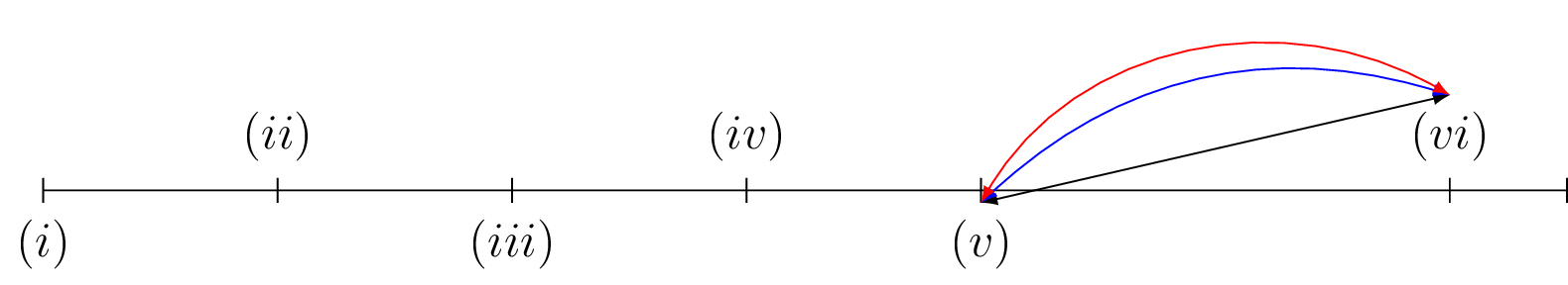
This is a LaTeX document that includes a TikZ picture. The picture is a number line with ticks marking various points on the line, and with labels "i" through "vi" beneath the line indicating the position of those ticks. There are three lines connecting the labels "v" and "vi," one straight, one bending left, and one curving upwards to the right. The second TikZ picture is commented out and is an alternate version of the first picture with different lines connecting "v" and "vi." The document class is "standalone" with a 12pt font size, and the "inputenc" package is used to support unicode characters.
Keywords
tikzpicture, draw, foreach, node, latex-latex, blue, red, bend left, out, in.
Source Code
\documentclass[12pt,a4paper]{standalone}
\usepackage[utf8]{inputenc}
\usepackage[T1]{fontenc}
\usepackage{tikz}
\begin{document}

	\begin{tikzpicture}
	\draw (0,0) -- (13,0);
	\foreach \x in {0,2,4,6,8,12,13}
	\draw (\x cm,3pt) -- (\x cm,-3pt);
	\draw (0,0) node[below=3pt] (a) {$(i)$} node[above=3pt] {};
	\draw (2,0) node[below=3pt] (b) {} node[above=3pt] {$(ii)$};
	\draw (4,0)  node[below=3pt]  {$(iii)$} node[above=3pt] (c) {};
	\draw (6,0) node[below=3pt](d) {} node[above=3pt] {$(iv)$};
	\draw (8,0) node[below=3pt](e) {$(v)$} node[above=3pt] {};
	\draw (12,0) node[above=3pt] (f) {$(vi)$} node[below=3pt] {};
	\draw[latex-latex]
	(e.north) -- (f.north);
	\draw[latex-latex,blue]
	(e.north) to[bend left] (f.north);
	\draw[latex-latex,red]
	(e.north) to[out=60,in=150] (f.north);
	\end{tikzpicture}\qquad
%	\begin{tikzpicture}
%	\draw (0,0) -- (13,0);
%	\foreach \x in {0,2,4,6,8,12,13}
%	\draw (\x cm,3pt) -- (\x cm,-3pt);
%	\draw (0,0) node[below=3pt] (a) {$(i)$} node[above=3pt] {};
%	\draw (2,0) node[below=3pt] (b) {} node[above=3pt] {$(ii)$};
%	\draw (4,0)  node[below=3pt]  {$(iii)$} node[above=3pt] (c) {};
%	\draw (6,0) node[below=3pt](d) {} node[above=3pt] {$(iv)$};
%	\draw (8,0) node[below=3pt](e) {$(v)$} node[above=3pt] {};
%	\draw (12,0) node[above=3pt] (f) {$(vi)$} node[below=3pt] {};
%	\draw[latex-latex]
%	(e.north|-f.north) -- (f.north);
%	\draw[latex-latex,blue]
%	(e.north|-f.north) to[bend left] (f.north);
%	\draw[latex-latex,red]
%	(e.north|-f.north) to[out=60,in=120] (f.north);
%	\end{tikzpicture}

\end{document}