Description
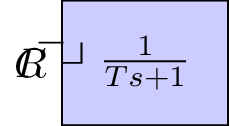
This code defines a simple block diagram using the TikZ package in LaTeX. The diagram consists of a summing junction, a proportional controller, a first-order lag, and an output. The block diagram is used to model a control system, where the input R is summed with the output of the proportional controller and then passed through a first-order lag before producing the output C. The code defines the shapes and styles of the blocks and arrows, and then places them in the diagram using the TikZ environment. The arrows represent the flow of signals in the control system, with labels indicating the signals' names. The code also includes mathematical symbols and expressions for the proportional controller and first-order lag.
Keywords
Keywords: tikz, math, block, controller, sum, input, output, arrows.
Source Code
\documentclass[tikz]{standalone}
\usepackage{amsmath,amssymb}
\usepackage{graphicx} % Required for inserting images

\tikzstyle{block} = [draw, fill=blue!20, rectangle, minimum height=3em, minimum width=4em]
\tikzstyle{controller} = [draw, fill=red!20, rectangle, minimum height=3em, minimum width=4em]
\tikzstyle{sum} = [draw, fill=blue!20, circle, node distance=1cm]
\tikzstyle{input} = [coordinate]
\tikzstyle{output} = [coordinate]


\begin{document}
\begin{tikzpicture}[auto, >=latex']
% Nodes
\node [input] (input) {};
\node [sum, right = 1cm of input] (sum) {};
\node [controller, right = 1cm of sum] (system) {$\frac{K}{s}$};
\node [block, right = 1cm of system] (system2) {$\frac{1}{Ts+1}$};
\node [output, right = 2cm of system2] (output) {};
\node [input, below = 0.5cm of system] (m) {};
% Arrows
\draw [draw,->] (input) -- node {$R$} (sum);
\draw [->] (sum) -- node {} (system);
\draw [->] (system) --  (system2);
\draw [->] (system2) -- node (y) {$C$}(output);
\draw [-] (y) |- (m) {} ;
\draw [->] (m) -| node[pos=0.99] {$-$}  node [near end] {} (sum);
\end{tikzpicture}
\end{document}