Description
This code is a LaTeX document that uses several packages, including circuitikz, graphicx, mathrsfs, latexsym, amssymb, and amsmath. It defines a new command \equal that is a shorthand for the equals sign.
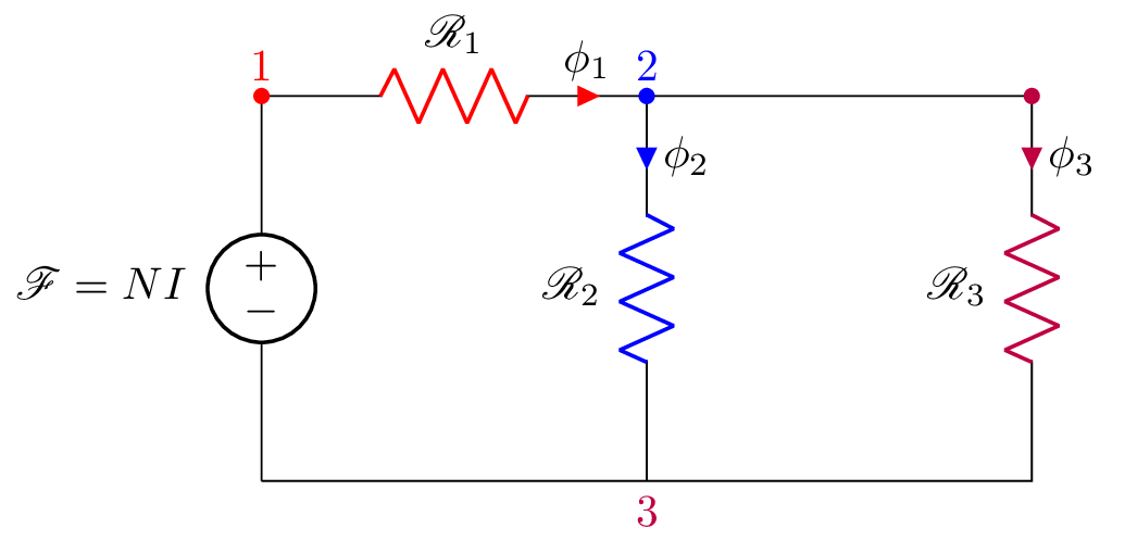
The document contains a circuitikz environment that draws an electrical circuit with three resistors and a voltage source. The circuit starts at the top with the voltage source labeled as . The circuit then goes down to resistor 1, which is labeled as and has a red color. The circuit continues to resistor 2, which is labeled as and has a blue color. The circuit then goes to resistor 3, which is labeled as and has a purple color. Resistor 3 is connected to the ground.
Each resistor has a label for the current flowing through it, which is denoted by a phi symbol with a subscript that matches the resistor number. There are also numbers and colors placed next to each resistor for identification purposes.
At the end of the document, there is a label for the figure with the name "fig:q1fig".
Keywords
circuit, circuitikz, voltage source, resistor, inductor, node, color.
Source Code
\documentclass{standalone}
\usepackage[american]{circuitikz}
\usepackage{graphicx}
\usepackage{mathrsfs}
\usepackage{latexsym,amssymb,amsmath}
\newcommand{\equal}{=}
\begin{document}
	\begin{circuitikz}
		\draw (0,3) to [V,l_=$\mathscr{F}\equal NI$] (0,0)
		(0,3) node[anchor=south] {$\textcolor{red}{1}$} to [R,i^>=$\phi_1$, l^=$\mathscr{R}_1$,*-,color=red] (3,3)
			node[anchor=south] {$\textcolor{blue}{2}$}
		to [R, l_= $\mathscr{R}_2$, *-, i>^=$\phi_2$,color=blue] (3,0)
			node[anchor=north] {$\textcolor{purple}{3}$}
		%(3,3) -- (6,3) to [L=$L$, i>^=$i_L(t)$, v=$v_L(t)$] (6,0) -- (0,0)
		(3,3) -- (6,3) to [R=$L$,l_=$\mathscr{R}_3$, i>^=$\phi_3$, *- ,color=purple] (6,0) -- (0,0)
		(6,0) -- (0,0)
		;\end{circuitikz}
	\label{fig:q1fig}
\end{document}