Description
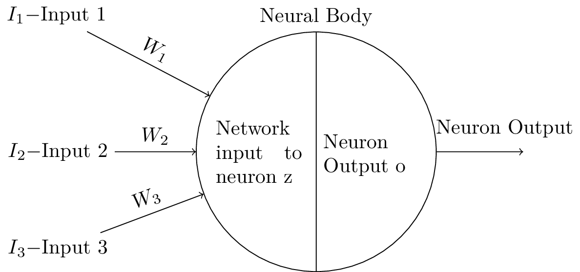
The code above produces a simple neural network diagram using TikZ. The diagram includes a single node representing a neuron, with its input and output labeled. The node is a circle split into two parts, with the top part containing the label "Network input to neuron z" and the bottom part containing the label "Neuron Output o". The node is rotated 90 degrees and labeled "Neural Body" using a label command.
The diagram also includes three input nodes labeled "Input 1", "Input 2", and "Input 3", positioned to the left and above the neuron. The input nodes are connected to the neuron using arrows labeled with the corresponding weights "W1", "W2", and "W3".
The TikZ library is used to define shapes, snakes, and shadows for the diagram, and to calculate node positions and create rounded corners for some of the connecting lines.
Keywords
tikz, shapes, snakes, calc, geometric, symbols, fit, positioning, shadows, circle, split, node, draw, rotate, align, label, rounded, corners, right, left, above, below, input, output, arrow
Source Code
\documentclass[tikz]{standalone}
\usepackage{tikz}
\usetikzlibrary{shapes,snakes}
\usetikzlibrary{calc, shapes.geometric,shapes.symbols,fit,positioning,shadows}
\begin{document}
\begin{tikzpicture}
\node [circle split,draw,rotate=90, align=center,label={[anchor=north, inner sep=0pt, yshift=1.2em] east:{\selectfont Neural Body}}] (part){\rotatebox{-90}{ \parbox{1.5cm}{Network input to neuron z} } \nodepart{lower} \rotatebox{-90}{\parbox{1.5cm}{Neuron Output o}} };
\draw[->,rounded corners=5pt] (part.south) -- ($(part.south)+(1.5,0)$);
\node[right = 3 em of part.south, label=Neuron Output] () {};

\node[above left = 0em and 10em of part.east] (t1) {$I_1-$Input 1};
\node[left = 4em of part.north] (t2) {$I_2-$Input 2};
\node[below left = 4em and 4em of part.north] (t3) {$I_3-$Input 3};

\draw[->] (t1) -- (part) node[midway,sloped,above] {$W_1$};
\draw[->] (t2) -- (part) node[midway,sloped,above] {$W_2$};
\draw[->] (t3) -- (part) node[midway,sloped,above] {$W_3$};
\end{tikzpicture}
\end{document}