Description
The code above is a LaTeX document that defines an adigraph (a directed graph) using the "adigraph" package. The adigraph is defined using the \NewAdigraph command, which takes two arguments: the name of the adigraph ("myAdigraph" in this case) and a specification of the nodes and edges of the graph.
The node and edge specification is written in the following format: nodeName: x,y; edgeStartNode,edgeEndNode:weight:options;
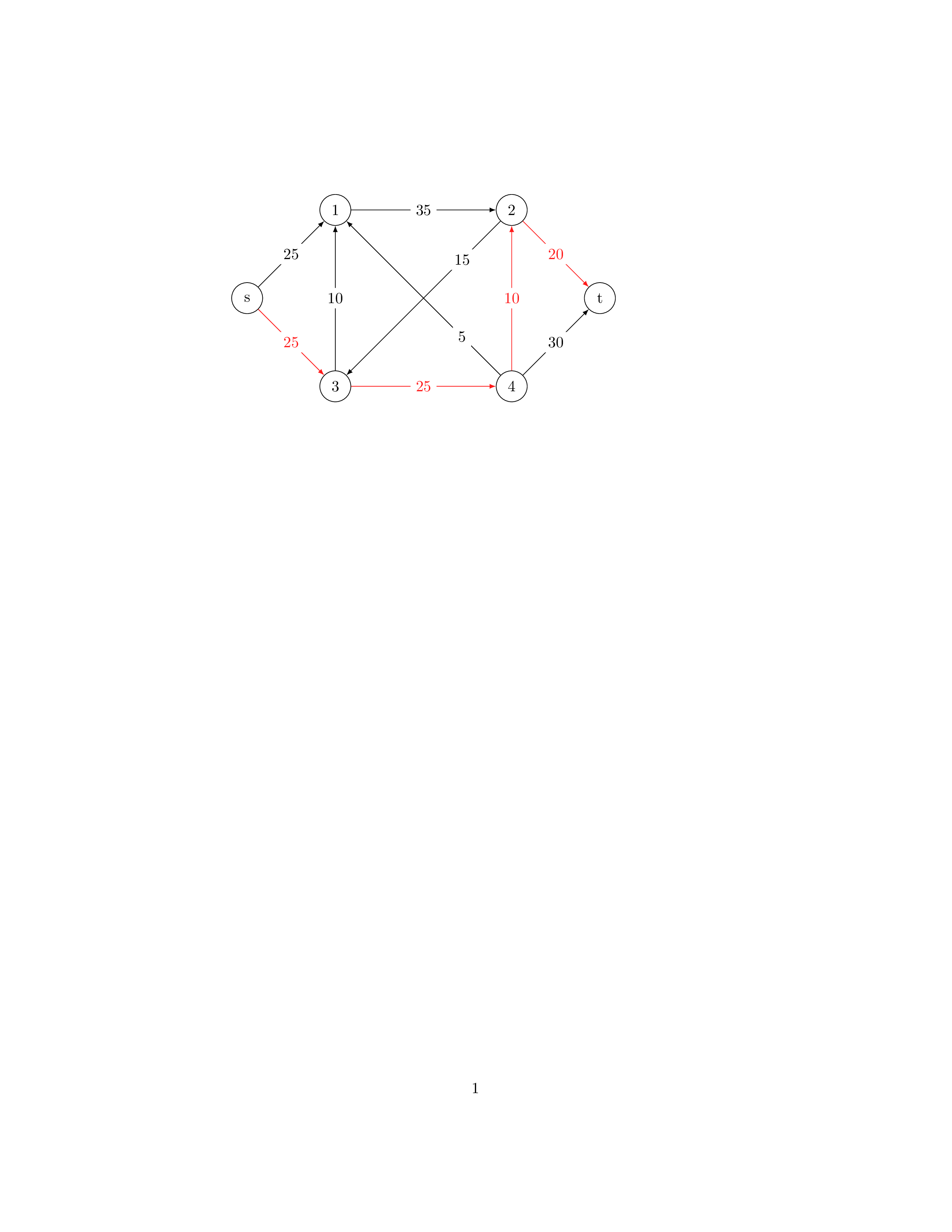
In this particular adigraph, there are six nodes named s, 1, 2, 3, 4, and t, and ten directed edges between them.
After defining the adigraph, the code uses the \myAdigraph command to draw the graph. The argument to this command specifies the order in which the nodes should be visited when drawing the graph, in this case s, 3, 4, 2, t.
The overall effect of the code is to generate a diagram of the defined adigraph, with the specified node and edge weights and options, using the "adigraph" package in LaTeX.
Keywords
adigraph, NewAdigraph, myAdigraph, s, t.
Source Code
\documentclass{article}
\nonstopmode
\usepackage{adigraph}
\begin{document}
\NewAdigraph{myAdigraph}{
s:0,0;
 1:2,2;
3:2,-2;
2:6,2;
 4:6,-2;
t:8,0;
}{
s,1:25;
s,3:25;
3,4:25;
1,2:35;
 2,t:20;
4,t:30;
3,1:10;
 4,2:10;
 2,3:15::near start;
 4,1:5::near start;
 }
\myAdigraph{
 s,3,4,2,t;
 }
\end{document}