Description
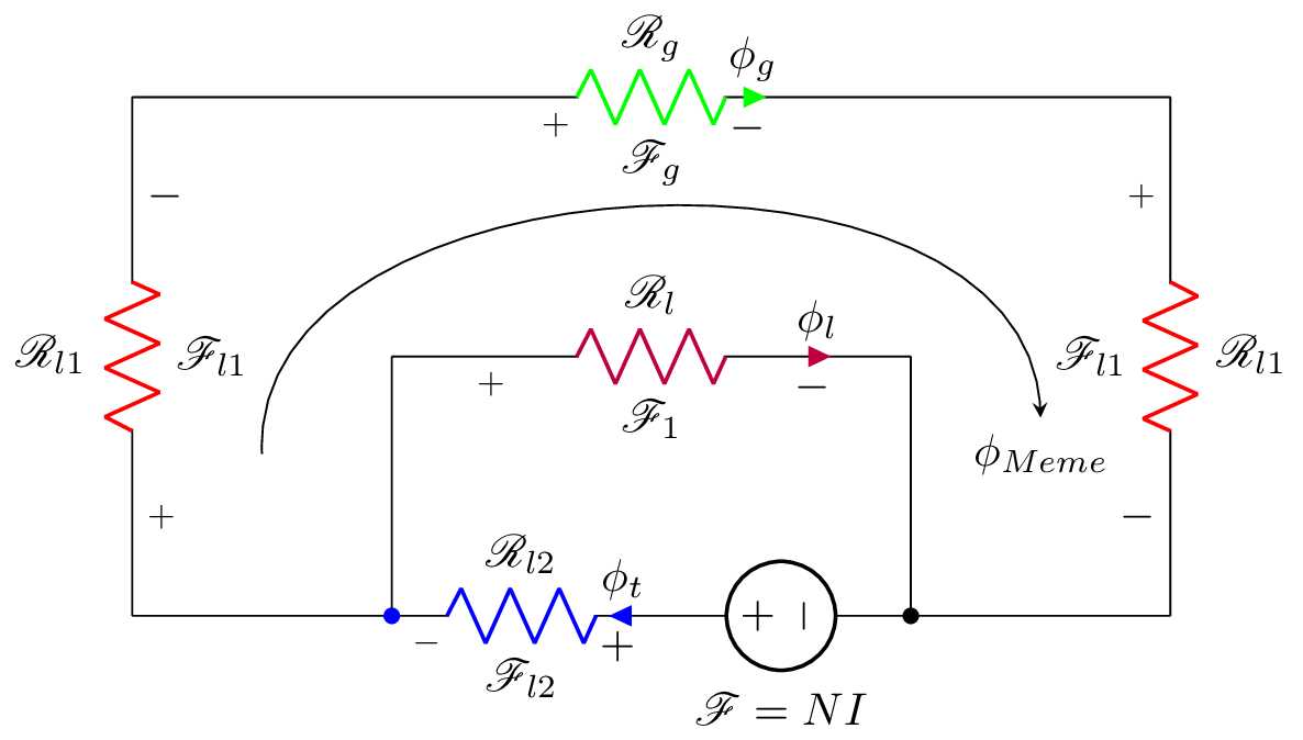
This is a LaTeX document that generates a circuit diagram using the circuitikz package. The circuit represents an electrical system with multiple resistors and a voltage source. The circuit consists of several components connected by wires. The circuit has three resistors, labelled as R_l, R_l1, and R_l2, and one voltage source labelled as . The circuit also includes several arrows that represent the flow of current and voltage, as well as labels to indicate the values of the different components. Finally, the diagram has a caption or title which says and is placed at the bottom of the image.
Keywords
circuitikz, graphicx, mathrsfs, latexsym, amssymb, amsmath, current, voltage, resistance, circuit, colors, nodes, arrows.
Source Code
\documentclass{standalone}
\usepackage[american]{circuitikz}
\usepackage{graphicx}
\usepackage{mathrsfs}
\usepackage{latexsym,amssymb,amsmath}
\newcommand{\equal}{=}
\begin{document}

			\begin{circuitikz}
				\draw (4,0) to [V,l_=$\mathscr{F}\equal NI$, -*] (6,0)
				(2,0) -- (2,2)
				(2,2) to [R,l^=$\mathscr{R}_{l}$,i^>=$\phi_l$, v_>=$\mathscr{F}_1$, color=purple] (6,2)
				(6,2) -- (6,0)
				(2,0) to [R,l^=$\mathscr{R}_{l2}$,i^<=$\phi_t$, v_<=$\mathscr{F}_{l2}$, *-, color=blue] (4,0)
				(2,0) -- (0,0)
				(0,0) to [R,l^=$\mathscr{R}_{l1}$, v_>=$\mathscr{F}_{l1}$, color=red]  (0,4)
				(6,0) -- (8,0)
				(8,4) to [R,l^=$\mathscr{R}_{l1}$, v_>=$\mathscr{F}_{l1}$, color=red]  (8,0)
				(0,4) -- (3,4)
				(3,4) to [R,l^=$\mathscr{R}_{g}$,i^>=$\phi_g$, v_>=$\mathscr{F}_{g}$, color=green] (5,4)
				(5,4) -- (8,4);
%				(0,0) to [R,l^=$\mathscr{R}_{g}$, v_<=$\mathscr{F}_1$, color=green] (4,0)
%				(0,2) to [R,l_=$0.5\mathscr{R}_{s}$, v^>=$\mathscr{F}_2$, color=blue] (4,2)
%				(4,2) -- (4,0)
			\node (phi) at (7.0,1.25) {$\phi_{Meme}$};
			\draw[-stealth]  (1,1.25) to [bend left=90] (phi);
			\end{circuitikz}
\end{document}