Description
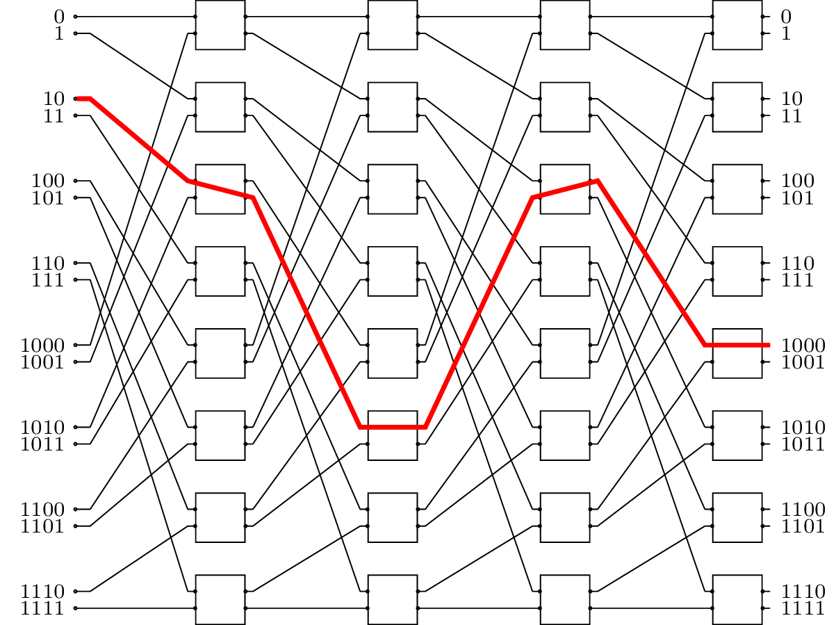
The given code is a LaTeX document that uses the TikZ package to draw a banyan network. The document class is set to "standalone", which means that the output will be a standalone image.
The TikZ library "sa-tikz" is also included, which provides some additional styles for drawing circuits.
The "module size", "pin length factor", "module ysep" and "module xsep" are TikZ styles that specify the size and spacing of the modules in the network.
Within the "tikzpicture" environment, a banyan network is drawn using the "banyan omega" style. The "P" parameter is set to 16, which specifies the size of the network.
The code then loops over each module and its inputs/outputs, and labels them with small numbers.
Finally, a red line is drawn between specific input and output ports in the network to illustrate the path of a signal through the network.
Keywords
tikz, sa-tikz, positioning, banyan omega, node, counter, mathbin, draw.
Source Code

\documentclass{standalone}

\usepackage{tikz}
\usepackage{sa-tikz}
\usetikzlibrary{positioning}
\begin{document}
\tikzset{module size=0.6cm,pin length factor=0.6,
module ysep=1.0, module xsep=3.5}

\begin{tikzpicture}[P=16]

\node[banyan omega={module label opacity=0}] {};
\newcounter{portb}
\setcounter{portb}{0}
\foreach \module in {1,...,8}{
    \foreach \port in {1,...,2}{
    \stepcounter{portb}
    \pgfmathbin{\theportb-1}
    \node[left] at (r0-\module-front input-\port)
    {\scriptsize{\pgfmathresult}};
    \node[right] at (r4-\module-front output-\port)
    {\scriptsize{\pgfmathresult}};
    }
}
\draw[red,ultra thick] (r0-2-front input-1) -- (r0-2-front output-1)--
(r1-3-front input-1) -- (r1-3-front output-2)-- (r2-6-front input-1)--
(r2-6-front output-1) -- (r3-3-front input-2) -- (r3-3-front output-1)--
(r4-5-front input-1) -- (r4-5-front output-1);
\end{tikzpicture}

\end{document}