Description
This is a LaTeX document which includes various packages and defines a new command. The packages included are circuitikz, graphicx, mathrsfs, latexsym, amssymb, and amsmath. The defined command is \equal, which outputs the equals sign =.
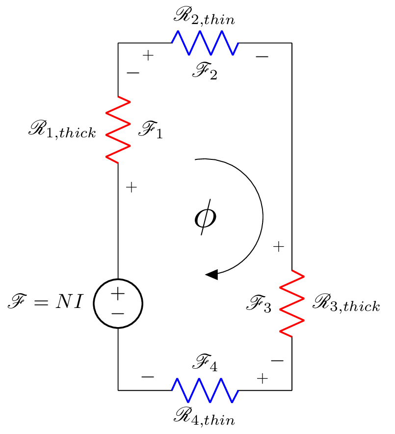
The document creates a circuit diagram using the circuitikz package, which includes a voltage source and four resistors connected in a specific pattern. The labels on the resistors are formatted using the math script font (\mathscr), and the colors of the resistors are specified. The circuit diagram is then labeled with the symbol phi using the arc command, and a scale of 2 is specified for the text. Finally, the document sets a label for the circuit diagram using the \label command.
Keywords
circuitikz, graphicx, mathrsfs, latexsym, amssymb, amsmath, voltage source, reluctance, node, arc
Source Code
\documentclass{standalone}
\usepackage[american]{circuitikz}
\usepackage{graphicx}
\usepackage{mathrsfs}
\usepackage{latexsym,amssymb,amsmath}

\newcommand{\equal}{=}
\begin{document}
	\begin{circuitikz}
		\draw (0,3) to [V,l_=$\mathscr{F}\equal NI$] (0,0) 	% "Voltage source for magentic circuit"
		(0,3) to [R,l^=$\mathscr{R}_{1,thick}$, v_>=$\mathscr{F}_1$, color=red] (0,6)	%Reluctance thick side
		(0,6) to [R, l^=$\mathscr{R}_{2,thin}$,v_>=$\mathscr{F}_2$, color=blue] (3,6)   %Reluctance thin side
		(3,6) -- (3,3)		% Connection R2, R3
	    (3,3) to [R, l^=$\mathscr{R}_{3,thick}$,v_>=$\mathscr{F}_3$, color=red] (3,0)   %Reluctance thick side
	     (3,0) to [R, l^= $\mathscr{R}_{4,thin}$,v_>=$\mathscr{F}_4$, color=blue] (0,0); %Reluctance thin side

	    \draw[thin, <-, >=triangle 45] (1.5,3) node[scale=2]{$\phi$}  ++(-90:1) arc (-90:100:1);
		\end{circuitikz}
	\label{fig:q1fig}
\end{document}