Description
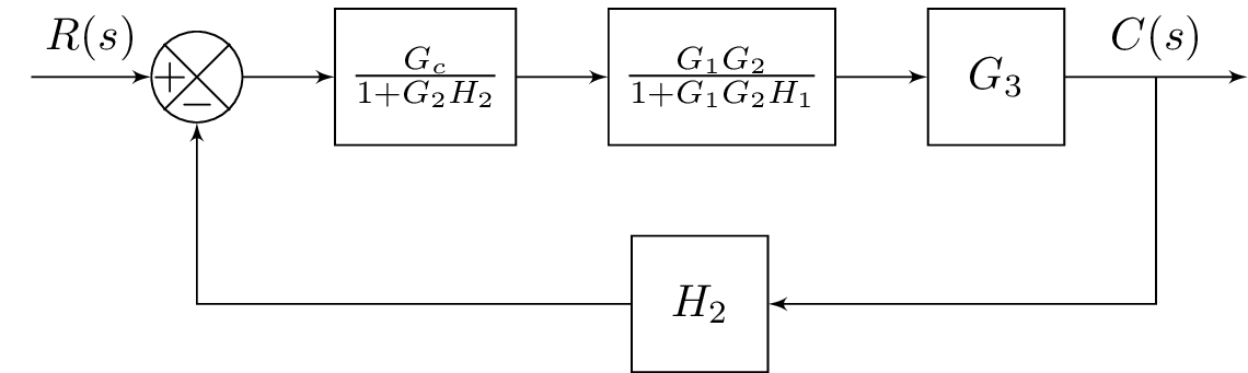
The code above generates a block diagram using the TikZ package. The diagram consists of several blocks and links that represent a control system. The system has an input labeled as , which is connected to a summing junction represented by the block labeled as "B". The output of the summing junction is then fed into a feedback loop through a series of blocks and links that represent a complex transfer function. The blocks included in the feedback loop are labeled as "Gc", "", and "G3". The output of the feedback loop is labeled as and connected to an output block labeled as "E". Finally, there is a branch from the "G3" block to a block labeled as "H2", which is then connected back to the summing junction "B" to complete the feedback loop.
Keywords
blox, tikz, positioning, bXInput, bXComp, bXLink, bXChain, bXOutput, bXBranchy, bXBlocr, bXLinkyx, bXLinkxy.
Source Code
\documentclass{standalone}

\usepackage{blox}
\usepackage{tikz}
\usetikzlibrary{positioning}
\newcommand{\equal}{=}
\usepackage{tikz}


\begin{document}

\begin{tikzpicture}
\bXInput{A}
\bXComp{B}{A}
\bXLink[$R(s)$]{A}{B}
\bXChain[2]{B}%
{Gc/$\frac{G_c}{1+G_2H_2}$,G1G2Feed/$\frac{G_1G_2}{1+G_1G_2H_1}$,G3/$G_3$}
\bXOutput[4]{E}{G3}
\bXLink[$C(s)$]{G3}{E}
\bXBranchy[5]{G3}{returnDown}

% return loop
\bXBlocr[5]{H2}{$H_2$}{returnDown}\bXLinkyx{G3-E}{H2}
\bXLinkxy{H2}{B}

%\bXReturn{G3-E}{B}{}
\end{tikzpicture}

\end{document}