Description
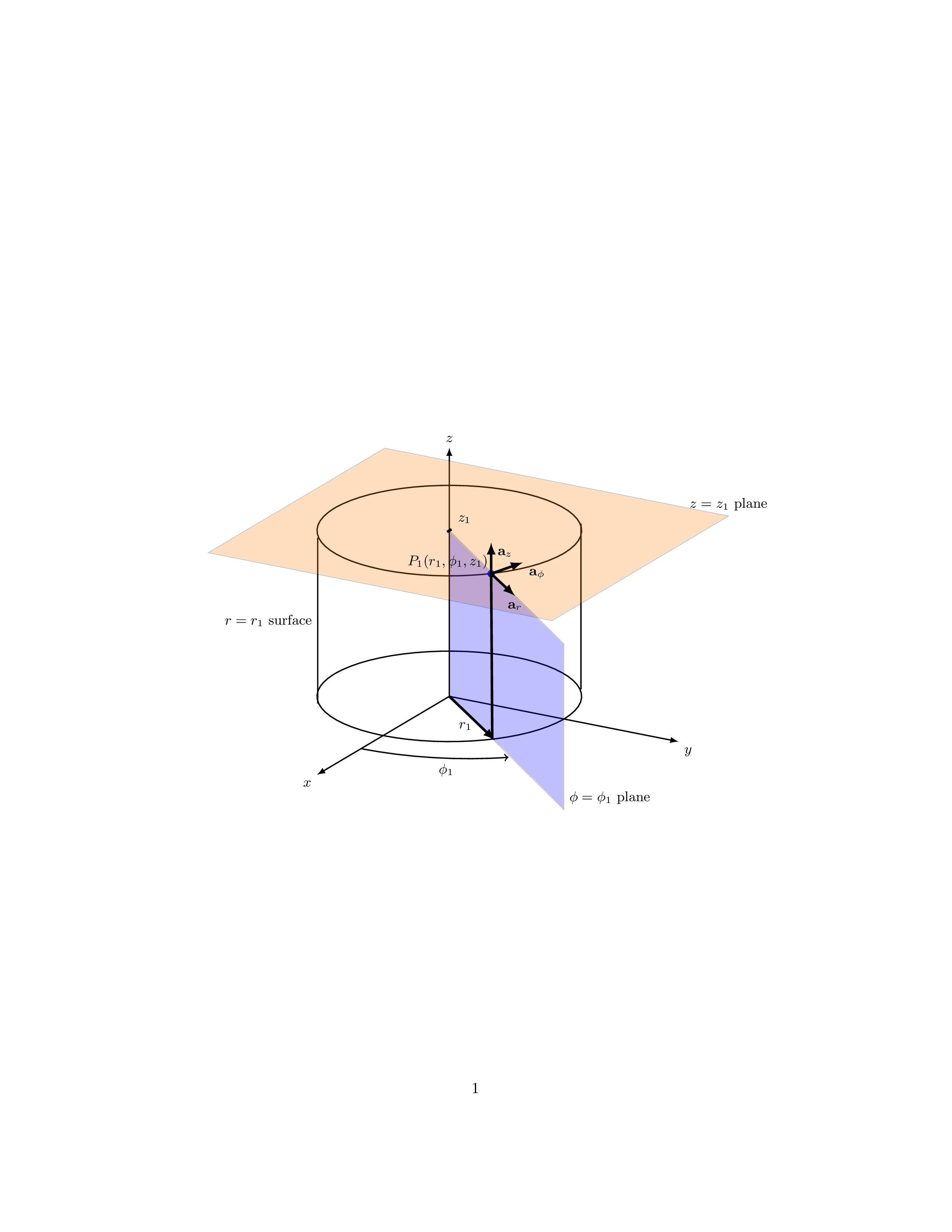
The code defines a 3D diagram of a point in cylindrical coordinates with a reference frame. It uses the TikZ and tikz-3dplot packages to generate the diagram.
The \tdplotsetmaincoords command sets the main coordinate system and the view angle of the diagram.
The tikzstyle command sets the font size for all nodes in the diagram.
The \draw commands draw the x, y, and z axes with arrows, a cylinder at the origin, and a cylinder at z=4 with an overlapping area to show the volume.
The \filldraw commands fill the overlapping area with a nearly transparent orange color and fill the bottom face of the top cylinder with a nearly transparent blue color.
The \draw commands also draw the r=r1 surface and the z=z1 and phi=phi1 planes, and label them accordingly.
The \node command labels the point P1 with its cylindrical coordinates.
The \draw commands also draw the unit vectors for the cylindrical coordinate system and label them accordingly.
Finally, the \draw command draws the angle phi1 and the radial distance r1, and labels them accordingly.
Keywords
tikz, tikz-3dplot, 3D, coordinates, axis, circle, filldraw, node, arrow, plane, phi, r, z.
Source Code
\documentclass{article}
\usepackage{tikz,tikz-3dplot}
\begin{document}

\begin{figure}
\centering
\tdplotsetmaincoords{70}{120}
\begin{tikzpicture}[tdplot_main_coords][scale=0.75]
\tikzstyle{every node}=[font=\small]
\draw[thick,-latex] (0,0,0) -- (6,0,0) node[anchor=north east]{$x$};
\draw[thick,-latex] (0,0,0) -- (0,6,0) node[anchor=north west]{$y$};
\draw[thick,-latex] (0,0,0) -- (0,0,6) node[anchor=south]{$z$};
\draw [thick](0,0,0) circle (3);
\draw [thick](0,0,4) circle (3);
\draw [thick](1.9,-2.35,0) -- (1.9,-2.35,4) node[midway, left]{$r=r_1$ surface};
\draw [thick](-1.9,2.35,0) -- (-1.9,2.35,4);
\filldraw[fill=orange, nearly transparent] (-4,-4,4) -- (4,-4,4) --  (4,5,4) -- (-4,5,4) -- (-4,-4,4);
\filldraw[fill=blue, nearly transparent] (0,0,4) -- (5.2,6,4) --  (5.2,6,0) -- (0,0,0) -- (0,0,4);
\filldraw [color=blue](2,2.25,4) circle (0.075cm) ;
\draw (-4,5,4) node[anchor=south]{$z=z_1$ plane};
\draw (5.2,6,0) node[anchor=south west]{$\phi=\phi_1$ plane};
\node at (1.8,1,4)  { $P_1(r_1,\phi_1,z_1)$};
\draw[ultra thick,-latex](2,2.25,4) -- (3,3.45,4) node[anchor=north] {$\mathbf{a}_r$};
\draw[ultra thick,-latex](2,2.25,4) -- (1,2.5,4) node[anchor=north west] {$\mathbf{a}_\phi$};
\draw[ultra thick,-latex](2,2.25,4) -- (2,2.25,4.75) node[anchor=north west] {$\mathbf{a}_z$};
\draw [thick,->](4,0,0) arc (0:45:4 and 4.5);
\draw (3.6,2,0) node[anchor=north] {$\phi_1$};
\draw[ultra thick,-latex](0,0,0) -- (2,2.35,0);
\draw (1,1,0) node[anchor=north] {$r_1$};
\draw [ultra thick] (2,2.25,4)--(1.95,2.25,0);

\draw[ultra thick](0.1,0,4) -- (-0.1,0,4) node[anchor=south west] {$z_1$};
\end{tikzpicture}
\end{figure}
\end{document}