Description
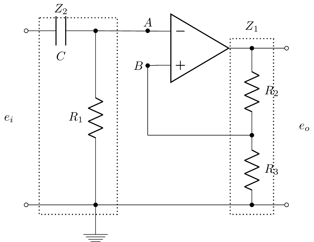
The code above is a LaTeX document that generates a circuit diagram using the circuitikz package. The circuit diagram consists of an input voltage source labeled , a capacitor labeled , a resistor labeled , an operational amplifier, two resistors labeled and , and an output voltage source labeled . The circuit is drawn using various commands from the circuitikz package, such as "to" for drawing wires and "node" for labeling components. The "dotted" and "rectangle" commands are used to draw boxes around components and , respectively. The document uses various LaTeX packages such as graphicx, mathrsfs, amsmath, and amssymb to generate the circuit and add math symbols.
Keywords
circuitikz, graphicx, mathrsfs, latexsym, amssymb, amsmath.
Source Code
\documentclass{standalone}
\usepackage[american]{circuitikz}
\usepackage{graphicx}
\usepackage{mathrsfs}
\usepackage{latexsym,amssymb,amsmath}
\newcommand{\equal}{=}
\begin{document}
		\begin{circuitikz}
		%\draw (0,4) to [open,v^>=$v_1(t)$,o-o]  (0,0) -- Open Short
		\draw (0,6) to [open,l_=$e_i$,o-o]  (0,1) % input
			(0,6) to  [C, l_= $C$,-*] (2,6)	%C
			(1,6) node[] (Z2) {}	% used for drawing rectangle
			(2,6) to  [R, l_=$R_1$,-*] (2,1)	%R1
			node[] (Z2end) {}	% used for drawing rectangle
			(2,1) -- (2,0.5) node[ground]{}	%ground
			(5, 5.5) node[op amp] (opamp) {}
			(2,	6) to [open, -*] (3.5,6) node[above]{$A$}
			(2,6) -- (opamp.-)
		     (3.5,5) node[left]{$B$} to [short,*-] 	(opamp.+)
		     (opamp.out)  to [short,-*]  (6.5,5.5)
		     node[] (Z1) {}	% used for drawing rectangle
		     to [R, l^=$R_2$,-*] (6.5,3) %R2
		     to [R, l^=$R_3$, -*] (6.5,1)
		      node[] (Z1end) {} % used for drawing rectangle
		     (6.5,3) -- (3.5,3)	% connect B to middle of resistors
		     (3.5,3) -- (3.5,5)	% vertical connection to B
			(6.5,5.5) -- (7.5,5.5)
			(7.5,5.5) to [open,l^=$e_o$,o-o]  (7.5,1) % output
			(0,1) -- (7.5,1) % wire
			;
			\draw[thick,dotted]     ($(Z1.north west)+(-0.5,0.15)$) rectangle ($(Z1end.south east)+(0.5,-0.15)$);
			\draw (Z1.north) +(0,0.5) node {$Z_1$};
			\draw[thick,dotted]     ($(Z2.north west)+(-0.5,0.25)$) rectangle ($(Z2end.south east)+(0.5,-0.15)$);
			\draw (Z2.north) +(0,0.5) node {$Z_2$};
	\end{circuitikz}
\end{document}