Description
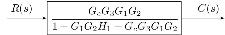
The code above is a LaTeX document that creates a block diagram using the blox and tikz packages. The diagram consists of a feedback control system with an input labeled "R(s)" and an output labeled "C(s)." The input is connected to a block labeled "C" which has a transfer function of and is then connected to the output. The labels for the input and output are aligned with the corresponding arrows using the \bXLink command. The \cfrac command is used to display a fraction with larger numerator and denominator. The amsmath and amssymb packages are used for math symbols and formatting.
Keywords
amsmath, amssymb, blox, tikz, block diagram, control system, feedback control, transfer function
Source Code
\documentclass{standalone}
\usepackage{amsmath}  % For math
\usepackage{amssymb}  % For more math

\usepackage{blox}
\usepackage{tikz}
\begin{document}
\begin{tikzpicture}
\bXInput{A}
\bXBloc[4]{C}{$\cfrac{G_cG_3G_1G_2}{1+G_1G_2H_1+G_cG_3G_1G_2}$}{A}
\bXOutput[4]{E}{C}
\bXLink[$R(s) \quad $]{A}{C}
\bXLink[$\quad C(s)$]{C}{E}
\end{tikzpicture}

\end{document}