Description
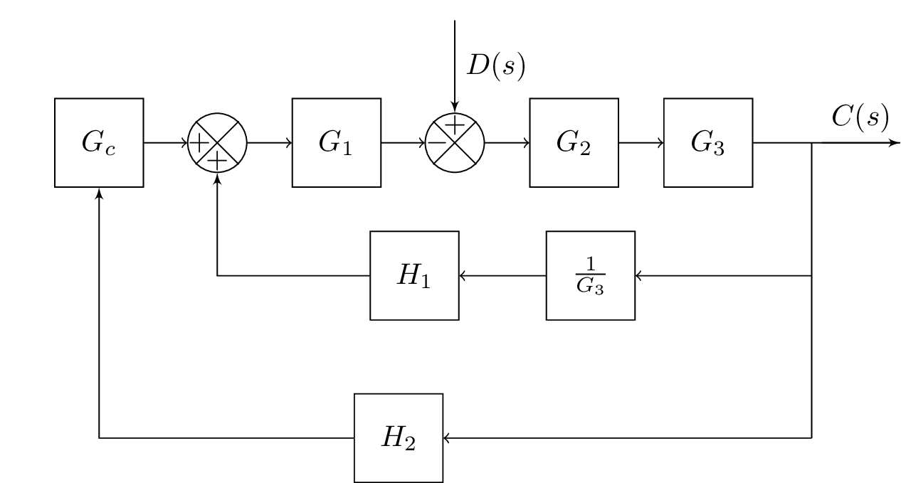
The LaTeX code above defines a standalone document with a TikZ picture containing a block diagram. The diagram represents a control system with multiple components, including several blocks (Gc, G1, G2, G3, H1, and H2) and several adders that sum the inputs from different blocks. The diagram also includes several branches and connections between the different components. The code uses the blox and tkz-euclide packages to draw the blocks and geometric figures, and it defines custom styles for the connections between blocks. The diagram represents a complex system with multiple inputs and outputs, and it can be customized and extended by changing the values and parameters of the different components.
Keywords
standalone, blox, tikz, positioning, intersections, tkz-euclide, Input, Bloc, Comp, Sum, Branch, Link, Output, connect, equal.
Source Code
\documentclass{standalone}

\usepackage{blox}
\usepackage{tikz}
\usetikzlibrary{positioning}
\newcommand{\equal}{=}
\usepackage{tikz}
\usetikzlibrary{intersections}
\usepackage{tkz-euclide}
% Radius for arc over intersection
\def\radius{1.mm}

\tikzset{
	connect/.style args={(#1) to (#2) over (#3) by #4}{
		insert path={
			let \p1=($(#1)-(#3)$), \n1={veclen(\x1,\y1)},
			\n2={atan2(\y1,\x1)}, \n3={abs(#4)}, \n4={#4>0 ?180:-180}  in
			(#1) -- ($(#1)!\n1-\n3!(#3)$)
			arc (\n2:\n2+\n4:\n3) -- (#2)
		}
	},
}

\begin{document}
\begin{tikzpicture}
\bXInput{input}				% Input
%\bXBranchx[0]{input}{GcLeft}
%\bXComp{adder1}{input}			% First adder
%\bXLink[$R(s)$]{input}{adder1}	% Input Label
\bXBloc[1.5]{Gc}{$G_c$}{input}			%BLock Gc
\bXSumb{adder2}{Gc}		% second adder
\bXBloc[1.5]{G1}{$G_1$}{adder2}	% G1 Block
\bXCompSum{adder3}{G1}{+}{}{-}{}		% third adder --suma variant
\bXBloc[1.5]{G2}{$G_2$}{adder3}	% G2 Block
\bXBranchy[-4.5]{adder3}{adder3up3} % adder3 up 3 units
\bXLink[$D(s)$]{adder3up3}{adder3}

%\bXBranchx[3]{G2}{G2Right15}		% Right of G2 1.5 units
\bXBloc[1.5]{G3}{$G_3$}{G2}		% G3 Block
\bXBranchx[3.5]{G3}{G3Right15}		% Right of G3 1.5 units
\bXBranchy[4.5]{G3Right15}{invG3Right}	% Right from G2 1.5 units right and 3 units down
\bXBloc[-9]{invG3}{$\frac{1}{G_3}$}{invG3Right}	% H1 Block
\bXBloc[-9]{H1}{$H_1$}{invG3}	% H1 Block
\bXBranchy[10]{G3Right15}{outputDown10}

\bXBloc[-15.5]{H2}{$H_2$}{outputDown10}
\bXOutput[3]{end}{G3Right15}

\draw[->] (Gc) -- (adder2);
\draw[->] (adder2) -- (G1);
\draw[->] (G1)  -- (adder3);
\draw[->] (adder3) -- (G2);
\draw[-] (G3) -- (end);
%\draw[-] (G2Right15.center) -- (G2Right15Down3.center);
\draw[-] (G3Right15.center) -- (outputDown10.center);
\draw[->] (outputDown10.center) -- (H2);
\draw[->] (G2) -- (G3); % Connect G2 and G3
\draw[->] (invG3Right.center) -- (invG3);
\draw[->] (invG3) -- (H1);
\bXLinkxy{H2}{Gc}
\bXLink[$C(s)$]{G3Right15}{end}	% Output Label
\bXLinkxy{H1}{adder2}
\end{tikzpicture}
\end{document}