Description
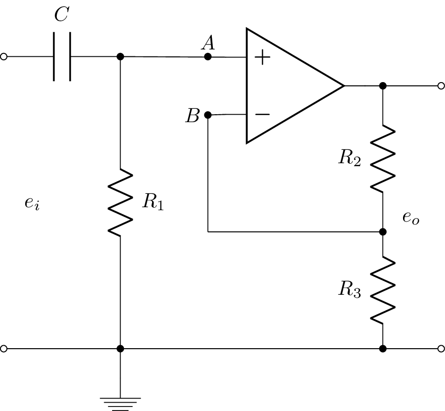
The code above is a LaTeX document that creates a circuit diagram using the circuitikz package. The circuit diagram shows an op-amp voltage amplifier with an input voltage source e_i and output voltage source e_o. The op-amp is connected to a capacitor C and a resistor R_1 on the input side, and to two resistors R_2 and R_3 on the output side. The input and output sources are connected to open circuit symbols, which indicate that they are not connected to anything else in the circuit. The op-amp is represented by a rectangular box with a + and - sign, which denotes its non-inverting and inverting inputs, respectively. The circuit is drawn using various commands, including draw, to, open, node, ground, and short. The values of the components in the circuit are specified using labels, such as $C$, $R_1$, $R_2$, and $R_3$.
Keywords
circuitikz, graphicx, mathrsfs, latexsym, amssymb, amsmath, op amp, C, R, ground
Source Code
\documentclass{standalone}
\usepackage[american]{circuitikz}
\usepackage{graphicx}
\usepackage{mathrsfs}
\usepackage{latexsym,amssymb,amsmath}
\newcommand{\equal}{=}
\begin{document}
		\begin{circuitikz}
		%\draw (0,4) to [open,v^>=$v_1(t)$,o-o]  (0,0) -- Open Short
		\draw (0,6) to [open,l=$e_i$,o-o]  (0,1) % input
			(0,6) to  [C, l^= $C$,-*] (2,6)	%C
			(2,6) to  [R, l^=$R_1$,-*] (2,1)	%R1
			(2,1) -- (2,0.5) node[ground]{}	%ground
			(5, 5.5) node[op amp,yscale=-1] (opamp) {}
			(2,	6) to [open, -*] (3.5,6) node[above]{$A$}
			(2,6) -- (opamp.+)
		     (3.5,5) node[left]{$B$} to [short,*-] 	(opamp.-)
		     (opamp.out)  to [short,-*]  (6.5,5.5)
		     to [R, l_=$R_2$,-*] (6.5,3) %R2
		     to [R, l_=$R_3$, -*] (6.5,1)
		     (6.5,3) -- (3.5,3)	% connect B to middle of resistors
		     (3.5,3) -- (3.5,5)	% vertical connection to B
			(6.5,5.5) -- (7.5,5.5)
			(7.5,5.5) to [open,l_=$e_o$,o-o]  (7.5,1) % output
			(0,1) -- (7.5,1) % wire
			;
	\end{circuitikz}
\end{document}