Description
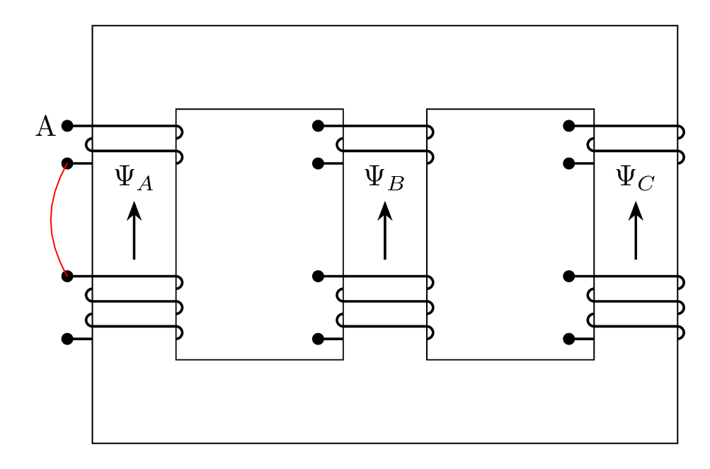
The code defines a TikZ picture that shows a box with three sub-boxes inside it. Each sub-box is defined using the "rectangle" command. There are also three input/output terminals ("terminal_a" and "terminal_b") defined using the "pic" command, and each terminal is connected to the sub-boxes using lines. The field lines are defined using another "pic" command, and a label is added using the "\tikzpictext" command. The red line connects two terminals. The overall style of the picture is set using various TikZ commands, such as "\draw" and "\node". The document class used is "standalone".
Keywords
tikz, arrows, pic, draw, fill, coordinate, path, node, rectangle, bend, text, angle, radius, arc, loop, red
Source Code

\documentclass[tikz,border=3mm]{standalone}

\usetikzlibrary{quotes,arrows.meta}

\begin{document}

\tikzset{
    terminal_a/.pic = {%
        \coordinate (-in) at (-3mm,0);
        \coordinate (-out) at (-3mm,-4.5mm);

        \path[fill] (-in) circle (2pt);
        \draw[thick] (-in)--(0,0)--++(0:1cm) arc[start angle=90, delta angle=-180, radius=.75mm];
        \draw[thick] (0,-1.5mm) arc[start angle=90, delta angle=180, radius=.75mm]--++(0:1cm) arc[start angle=90, delta angle=-180, radius=.75mm];
        \fill (-out) circle (2pt);
        \draw[thick] (-out) -- ++(0:3mm);
        },
    terminal_b/.pic = {%
        \coordinate (-in) at (-3mm,0);
        \coordinate (-out) at (-3mm,-7.5mm);

        \path[fill] (-in) circle (2pt);
        \draw[thick] (-in)--(0,0)--++(0:1cm) arc[start angle=90, delta angle=-180, radius=.75mm];
        \draw[thick] (0,-1.5mm) arc[start angle=90, delta angle=180, radius=.75mm]--++(0:1cm) arc[start angle=90, delta angle=-180, radius=.75mm];
        \draw[thick] (0,-4.5mm) arc[start angle=90, delta angle=180, radius=.75mm]--++(0:1cm) arc[start angle=90, delta angle=-180, radius=.75mm];
        \fill (-out) circle (2pt);
        \draw[thick] (-out) -- ++(0:3mm);
        },
    field/.pic = {
        \draw[thick,-Stealth] (0,0) -- (90:7mm) node[above] {\tikzpictext};
        }
}

\begin{tikzpicture}
\draw (0,0) rectangle (7,5);
\draw (1,1) rectangle (3,4);
\draw (4,1) rectangle (6,4);

\foreach \i/\j in {0/A,3/B,6/C}{
    \pic (upper-\j) at (\i,3.8) {terminal_a};
    \pic (lower-\j) at (\i,2) {terminal_b};
    \pic["$\Psi_\j$"] at ([xshift=5mm]\i,2.2) {field};
    }

\node[left] at (upper-A-in) {A};
\draw[red] (upper-A-out) to [bend right] (lower-A-in);

\end{tikzpicture}
\end{document}