Description
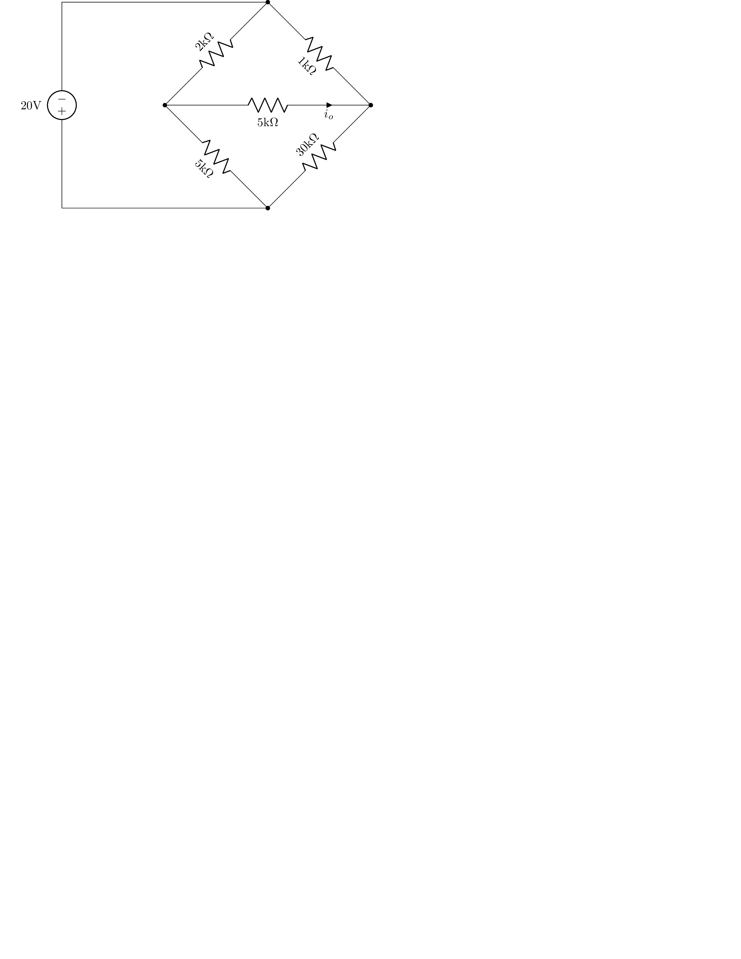
This is a LaTeX code that generates a circuit diagram using the circuitikz package. The circuit diagram depicts a voltage source connected to two half bridges, with a voltmeter connected across one of the resistors in the right half bridge. The siunitx and amsmath packages are also included.
The circuit diagram consists of several components and parameters specified using various circuitikz commands. The voltage source is created using the V command, with a voltage of 20 volts and labeled with the v parameter. The resistors are created using the R command, with their values specified using the l parameter, and their orientation specified using the - and * parameters. The voltmeter is created using another R command, and is labeled with the i parameter. The american voltages option is used to display voltages in the diagram in the American style.
Keywords
circuit, voltage, resistor, voltmeter.
Source Code
\documentclass[tikz]{standalone}
\usepackage{circuitikz}
\usepackage{siunitx}
\usepackage{amsmath,amssymb}
\begin{document}
\begin{circuitikz}[american voltages]
	% Voltage source
	\draw (0,0) to [V, v>=$20 \si{\volt}$](0, 6) to (6, 6)
	% Left half bridge
	to [R, l_=$2 \si{k\ohm}$, *-*] (3,3) % Top left resistor
	to [R, l_=$5 \si{k\ohm}$, -*] (6,0);  % Bottom left resistor
	% Right half bridge
	\draw (6,6)
	to [R, l_=$1 \si{k\ohm}$, -*] (9, 3) % Top right resistor
	to [R, l_=$30 \si{k\ohm}$, -*] (6,0)  % Bottom left resistor
	% Draw connection to (-) terminal of voltage source
	to (6, 0) to (0,0);

	% Draw voltmeter
	\draw (3, 3) to [R, l_=$5 \si{k\ohm}$,i_=$i_o$, -*] (9, 3);
\end{circuitikz}
\end{document}