Description
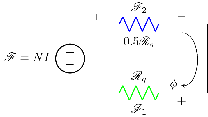
This code creates a circuit diagram using the circuitikz package in LaTeX. The circuit diagram shows a voltage source with label , where N and I are variables, connected in series with a resistor . Another resistor, , is connected in parallel to the voltage source, and the two components are connected in series to a ground node at the bottom of the diagram. The voltage across the resistor is labeled and is shown in green, while the voltage across the resistor is labeled and is shown in blue. A symbol is added next to the resistor and an arrow shows the direction of the current flow.
Keywords
circuitikz, graphicx, mathrsfs, latexsym, amssymb, amsmath, current source, resistor, voltage, arrow.
Source Code
\documentclass{standalone}
\usepackage[american]{circuitikz}
\usepackage{graphicx}
\usepackage{mathrsfs}
\usepackage{latexsym,amssymb,amsmath}
\newcommand{\equal}{=}
\begin{document}

			\begin{circuitikz}
				\draw (0,2) to [V,l_=$\mathscr{F}\equal NI$] (0,0)
				(0,0) to [R,l^=$\mathscr{R}_{g}$, v_<=$\mathscr{F}_1$, color=green] (4,0)
				(0,2) to [R,l_=$0.5\mathscr{R}_{s}$, v^>=$\mathscr{F}_2$, color=blue] (4,2)
				(4,2) -- (4,0);
			\node (phi) at (3.0,0.25) {$\phi$};
			\draw[-stealth]  (3.25,1.75) to [bend left=90] (phi);
			\end{circuitikz}
\end{document}