Description
This code defines a standalone LaTeX document with a TikZ environment for creating an electrical circuit diagram. It includes the necessary packages for creating circuit diagrams, using SI units, and typesetting mathematical symbols.
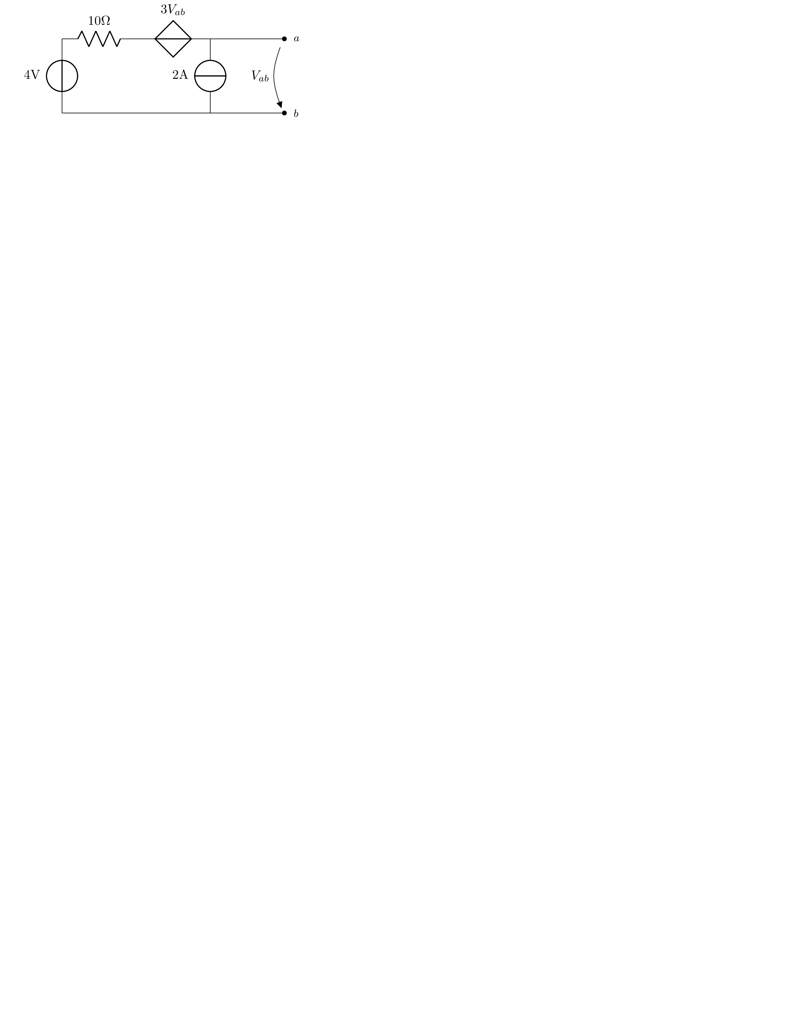
The circuit consists of a voltage source with a value of 4 volts connected in series to a resistor with a value of 10 ohms. The voltage at the top of the resistor is connected to a controlled voltage source with a voltage of 3 times the voltage between nodes a and b. The bottom of the controlled voltage source is connected to a current source with a value of 2 amperes. Nodes a and b are connected to the top and bottom of the circuit respectively. An open circuit element with a label of Vab is added to the right of the circuit to represent the voltage between nodes a and b.
Keywords
circuitikz, siunitx, voltage source, resistor, current-controlled voltage source, current source, open circuit.
Source Code
\documentclass[tikz]{standalone}
\usepackage{circuitikz}
\usepackage{siunitx}
\usepackage{amsmath,amssymb}
\begin{document}
\begin{circuitikz}
	\draw (0,2) to[V,l_=$4 \si{\volt}$] (0,0); %% Note _>= instead of >=
	\draw (0,2)to [R,l^=$10 \si{\ohm}$] (2,2);
	\draw (2,2)to [cV,l^=$3V_{ab}$] (4,2);
	\draw (4,0) to  [I,l^=$2\si{\ampere}$](4,2);
	\draw (4,2) to [short,-*] (6,2)
		node[label={[font=\footnotesize]right:$a$}] {};
	\draw (0,0) to [short,-*] (6,0)
		node[label={[font=\footnotesize]right:$b$}] {};
	\draw (6,2) to [open,v_>=$V_{ab}$] (6,0);
\end{circuitikz}
\end{document}