Description
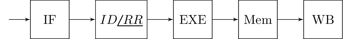
The code creates a block diagram using the "blox" package, where the blocks are connected in a chain. The "steinmetz" package is used to typeset the phase symbol. The "positioning" library is used to position the blocks. The diagram represents a simple pipelined processor consisting of five stages, identified as "IF", "ID", "EXE", "Mem", and "WB". The blocks are labeled with the corresponding stage names, except for the second block which is labeled as "". The input block is labeled as "E".
Keywords
TikZ, blox, steinmetz, positioning, circuits.
Source Code
\documentclass{standalone}

\usepackage{blox}
\usepackage{tikz}
\usepackage{steinmetz}
\usetikzlibrary{positioning}

\usetikzlibrary{circuits}
\begin{document}

\begin{tikzpicture}
\bXInput{E}
\bXChain[2]{E}%
{Md/IF,fred/$ID\phase{RR}$,head/EXE,Fun/Mem, Games/WB}
\end{tikzpicture}
\end{document}