Description
The code defines a TikZ picture that contains a module diagram with labeled boxes and arrows. The TikZ library positioning, matrix, and shapes.arrows are used. The tikzset command is used to define the styles for the different modules and arrows.
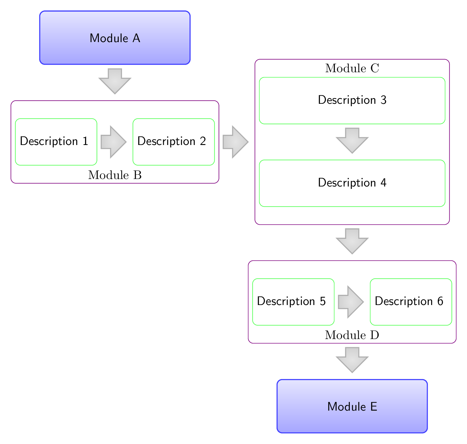
The diagram consists of five modules, labeled as A, B, C, D, and E, and labeled with descriptions. The module B is a matrix of two nodes with descriptions 1 and 2. Module C is a matrix of two nodes with descriptions 3 and 4. Module D is a matrix of two nodes with descriptions 5 and 6. Modules A and E are simple modules, and each has a down arrow pointing to the next module.
Arrows are drawn between the modules, with the arrow style depending on the direction. Modules A, C-1-1, C, and D have down arrows, while modules B-1-1, B, and D-1-1 have right arrows.
Keywords
tikz, positioning, matrix, shapes, arrows.
Source Code
\documentclass[border=3mm]{standalone}
\usepackage{tikz}
\usetikzlibrary{positioning,matrix,shapes.arrows}

\tikzset{
	modulematrix/.style={draw=blue!50!red,rounded corners,matrix of nodes,row sep=1cm,column sep=1cm,nodes={draw=green!70,align=center,font=\sffamily},inner ysep=0.5cm},
	module/.style={rounded corners, align=center, font=\sffamily, thick},
	simple module/.style={module, top color=blue!10, bottom color=blue!35, draw=blue!75, text width=40mm, minimum height=15mm},
	module down arrow/.style={module arrow, shape border rotate=-90},
	module right arrow/.style={module arrow},
	module arrow/.style={single arrow, single arrow head extend=2.5mm, draw=gray!75, inner color=gray!20, outer color=gray!35, thick, shape border uses incircle, anchor=tail,minimum height=0.7cm},
}
\begin{document}
	\begin{tikzpicture}
	\node [simple module] (mA) {Module A};
	\matrix[modulematrix,below=of mA,label={[anchor=south]below:Module B}] (mB) {Description 1 & Description 2 \\};
	\matrix[modulematrix,right=of mB,nodes={text width=5cm,align=center},label={[anchor=north]above:Module C}] (mC) {Description 3 \\ Description 4 \\};
	\matrix[modulematrix,below=of mC,label={[anchor=south]below:Module D}] (mD) {Description 5 & Description 6 \\};
	\node [simple module,below=of mD] (mE) {Module E};

	\foreach \n in {mA,mC-1-1,mC,mD}
	\node[module down arrow,below=1mm of \n] {};

	\foreach \n in {mB-1-1,mB,mD-1-1}
	\node[module right arrow,right=1mm of \n] {};
	\end{tikzpicture}
\end{document}