Description
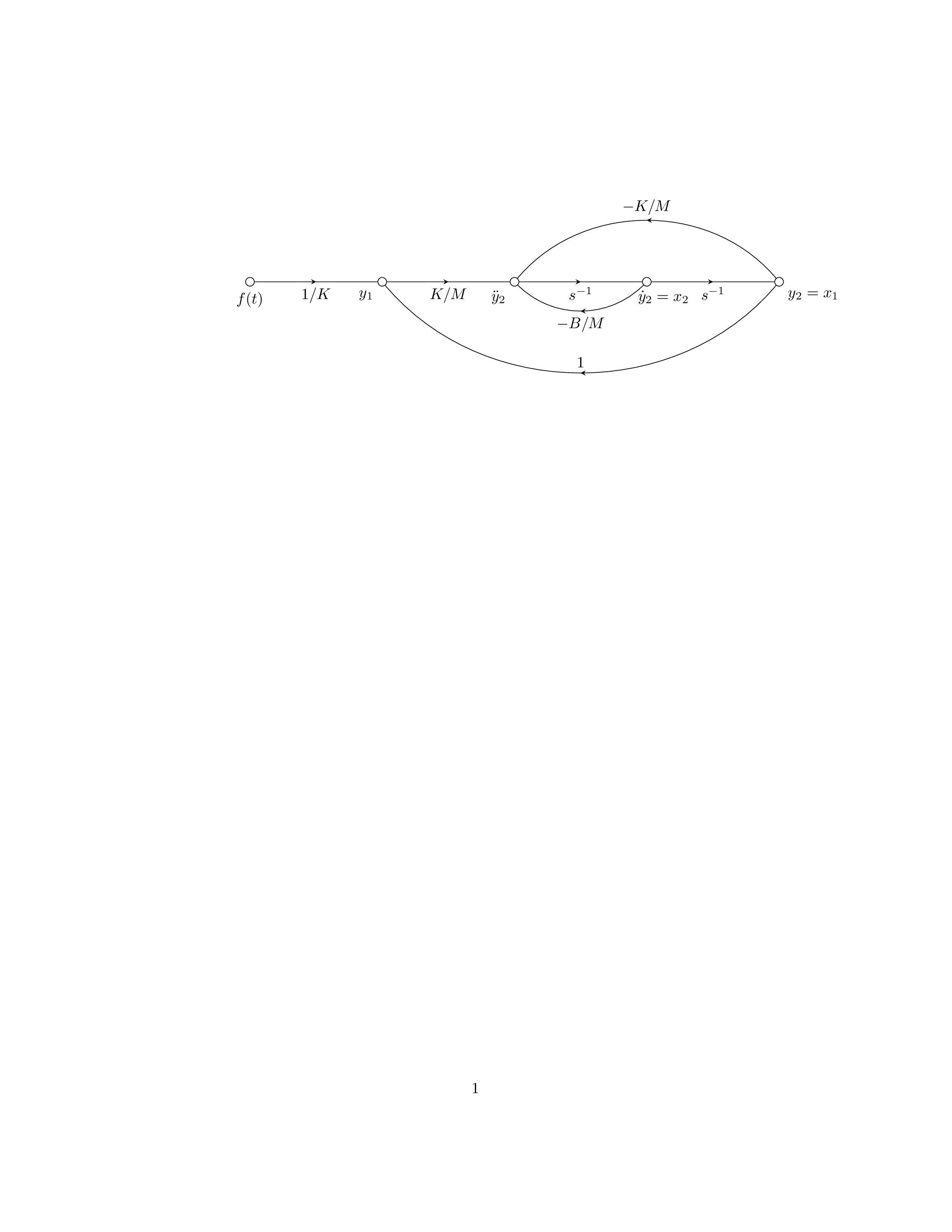
The code above is a LaTeX document that uses the TikZ package to create a diagram of a second-order mechanical system with a feedback control loop. The diagram consists of five nodes representing the different components of the system, namely the input function , the output , the intermediate state variable , and the two other intermediate variables and . The connections between the nodes are drawn as arrows with labeled markers representing the transfer functions of the components. The options and styles used in the TikZ picture include "label revd" which is a conditional that decides whether the label should be above or below the arrow depending on the value of the "labrev" boolean flag. The picture also defines a custom style called "amark" that applies a decoration to the arrow, consisting of a marker at the middle of the arrow with a label above or below it depending on the value of the "labrev" flag. Finally, the picture uses the "terminal" style to define the nodes, which are circles with an inner label and optional label position.
Keywords
tikz, decorations.markings, newif, terminal, amark
Source Code
\documentclass{article}
\usepackage{tikz}
\usetikzlibrary{decorations.markings}
\newif\iflabrev
\begin{document}
\begin{tikzpicture}
[
label revd/.is if=labrev,
%label revd/.default=true,
amark/.style={
            decoration={
                        markings,
                        mark=at position {0.5} with {
                                    \arrow{stealth},
                                    \iflabrev \node[above] {#1};\else \node[below] {#1};\fi
                        }
            },
            postaction={decorate}
},
terminal/.style 2 args={draw,circle,inner sep=2pt,label={#1:#2}},
]

%Place the nodes
\node[terminal={below}{$f(t)$}] (a) at (0,0) {};
\node[terminal={below left}{$y_1$}] (b) at (3cm,0) {};
\node[terminal={below left}{$\ddot{y}_2$}] (c) at (6cm,0) {};
\node[terminal={[xshift=-4mm]below right}{$\dot{y}_2=x_2$}] (d) at (9cm,0) {};
\node[terminal={below right}{$y_2=x_1$}] (e) at (12cm,0) {};
%Draw the connections
\draw[amark=$1/K$] (a) to (b);
\draw[amark=$K/M$] (b) to (c);
\draw[amark=$s^{-1}$] (c) to (d);
\draw[amark=$s^{-1}$] (d) to (e);
\draw[amark=$-B/M$] (d) to[bend left=45] (c);
\draw[amark=$1$,label revd] (e) to[bend left=50] (b);
\draw[amark=$-K/M$,label revd] (e) to[bend right=50] (c);
\end{tikzpicture}
\end{document}