Description
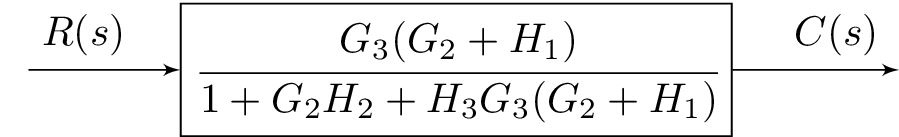
The code above is a LaTeX code for creating a block diagram using the blox and tikz packages. The block diagram represents a control system with a single input, , and a single output, . The system is represented by a single block labeled C, with transfer function , and with input connected to the input A and output connected to the output E. There are also labels for the input and output signals, with $R(s) \quad $ representing the input signal and $\quad C(s)$ representing the output signal. The packages amsmath and amssymb are included for typesetting math equations. The standalone document class is used to create a standalone image of the block diagram.
Keywords
tikzpicture, bXInput, bXBloc, bXOutput, bXLink, s, G_3, G_2, H_1, H_2, H_3, R(s), C(s)
Source Code
\documentclass{standalone}
\usepackage{amsmath}  % For math
\usepackage{amssymb}  % For more math

\usepackage{blox}
\usepackage{tikz}
\begin{document}
\begin{tikzpicture}
\bXInput{A}
\bXBloc[4]{C}{$\cfrac{G_3(G_2+H_1)}{1+G_2H_2+H_3G_3(G_2+H_1)}$}{A}
\bXOutput[4]{E}{C}
\bXLink[$R(s) \quad $]{A}{C}
\bXLink[$\quad C(s)$]{C}{E}
\end{tikzpicture}

\end{document}