Description
This is a LaTeX code that creates an electronic circuit diagram using the circuitikz package. The code defines the document class as standalone and then imports the necessary packages graphicx, mathrsfs, latexsym, amssymb, and amsmath. It also defines a new command \equal that represents the equals sign.
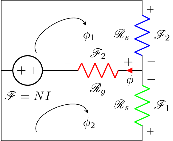
The circuit diagram consists of a voltage source on the left side, two resistors of the same value connected in series in the center, and a third resistor connected in parallel to the first two. The values of the resistors are represented by the variables R_s and R_g. The voltage source is represented by the symbol $\mathscr{F}\equal NI$.
The resistors are color-coded in green and blue, and the resistor in parallel is color-coded in red. The direction of the current flow in the parallel resistor is represented by the variable $\phi$. Two labels $\phi_1$ and $\phi_2$ are also added to the circuit diagram using node.
Keywords
circuitikz, graphicx, mathrsfs, latexsym, amssymb, amsmath, circuit, voltage, resistance, current, arrows.
Source Code
%corresponds to question 4, ELEC 370 assignment 1.
\documentclass{standalone}
\usepackage[american]{circuitikz}
\usepackage{graphicx}
\usepackage{mathrsfs}
\usepackage{latexsym,amssymb,amsmath}
\newcommand{\equal}{=}
\begin{document}

			\begin{circuitikz}
				\draw (0,2) to [V,l_=$\mathscr{F}\equal NI$] (1.5,2)
				(0,0) --(0,4)
				(0,0) -- (4,0)
				(0,4) -- (4,4)
				(4,0) to [R,l^=$\mathscr{R}_{s}$, v_>=$\mathscr{F}_1$, color=green] (4,2)
				(4,4) to [R,l_=$\mathscr{R}_{s}$, v^>=$\mathscr{F}_2$, color=blue] (4,2)
				(1.5,2)  to [R,l_=$\mathscr{R}_{g}$, v^<=$\mathscr{F}_2$,i_<=$\phi$, color=red] (4,2);

				\node (phi) at (2.5,3) {$\phi_1$};
				\draw[-stealth]  (1,2.5) to [bend left=90] (phi);

				\node (phi) at (2.5,0.5) {$\phi_2$};
				\draw[-stealth]  (1,0.25) to [bend left=90] (phi);
			\end{circuitikz}
\end{document}