Description
The given LaTeX code generates a block diagram for a control system. It starts by defining a few variables such as \equal for the equal sign, and the radius of an arc over the intersection. Then it defines a style called connect that can be used to draw a curved line between two points. The actual diagram is created in a tikzpicture environment.
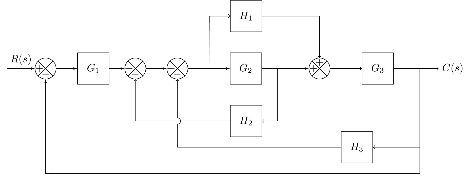
The diagram starts with an input block, labeled as A. A summing block is added next, labeled as B. A line is drawn with the label R(s) from A to B, indicating the input to the summing block. Block G1 is added with a gain of 2, labeled as C, and a line is drawn from B to C. Two more summing blocks are added, labeled as D and E, respectively. A branch is added from E for two blocks, H1 and G2, with G2 having a gain of 2, labeled as EH2. Block H1 is positioned above G1 using a branch. Another branch is added from G2 to block H2 with a gain of -1.5.
The other branch from E is used to add two more blocks, H2 and G3. Block H2 has a gain of -4.5 and is placed below the branch. Another summing block is added below H2, labeled as adder4, and a line is drawn from EH2 to adder4, indicating the input to adder4. Block G3 is added below adder4 with a gain of 3. The output of G3 is connected to the final block, which is labeled as C(s).
Lastly, some connections between blocks are made using lines and arrows. The connect style is used to draw a curved line from adder3down to E with a 3pt gap over the intersection with H2 to adder2down. A line is drawn from H2Block to adder2down, and from adder4up to adder4. The final output is connected to G3Block using an arrow, and a line is drawn from H3Block to adder3down. Finally, the last connection is made between BranEndReturn and B.
Keywords
The keywords for the LaTeX diagram above are: TikZ, nodes, edges, graphs, styles, labels, arrows, paths, positioning.
Source Code
% Block diagram in control system - complete

\documentclass{standalone}

\usepackage{blox}
\usepackage{tikz}
\usetikzlibrary{positioning}
\newcommand{\equal}{=}
\usepackage{tikz}
\usetikzlibrary{intersections}
\usepackage{tkz-euclide}
% Radius for arc over intersection
\def\radius{1.mm}

\tikzset{
	connect/.style args={(#1) to (#2) over (#3) by #4}{
		insert path={
			let \p1=($(#1)-(#3)$), \n1={veclen(\x1,\y1)},
			\n2={atan2(\y1,\x1)}, \n3={abs(#4)}, \n4={#4>0 ?180:-180}  in
			(#1) -- ($(#1)!\n1-\n3!(#3)$)
			arc (\n2:\n2+\n4:\n3) -- (#2)
		}
	},
}

\begin{document}
\begin{tikzpicture}
\bXInput{A}				% Input
\bXComp{B}{A}			% First adder
\bXLink[$R(s)$]{A}{B}	% Input Label
\bXBloc[2]{C}{$G_1$}{B}	% Block G1
\bXLink{B}{C}			% First added -- G1
\bXComp{D}{C}			% Second adder
\bXComp{E}{D}			% Third adder
\bXBranchx[3]{E}{EH1}	% Branch for H1, G2
\bXBloc[2]{EH2}{$G_2$}{EH1}	% Block G2
\bXBranchy[-5]{EH2}{EV2}	% Branch up for H1 -- above G1
\bXBloc[-1.5]{H2}{$H_1$}{EV2}	% Block H1
\bXBranchx[-3.5]{H2}{H2left}	% Branch for H1, G2

\bXBranchx[3]{EH2}{Bran2}		% Branch after G2 and for H2
\bXBranchy[5]{Bran2}{Bran2Down}	% beneath branch 2
\bXBloc[-4.5]{H2Block}{$H_2$}{Bran2Down}
\bXSuma{adder4}{Bran2}
\bXLink{C}{D}
\bXLink{D}{E}
\bXLink{E}{EH2}
\bXLink{EH2}{adder4}		% G2 to adder

\bXBloc[3]{G3Block}{$G_3$}{adder4} % G3
\bXBranchx[4]{G3Block}{BranEnd} % branch before output
\bXBranchy[7.5]{BranEnd}{H3BlockRight} % Right H3 Block
\bXBranchy[2.5]{H3BlockRight}{BranEndReturn} % Right H3 Block
\bXBranchy[7.5]{E}{adder3down} % Below adder3
\bXBloc[-7.5]{H3Block}{$H_3$}{H3BlockRight}	% H3 Block
\draw[-] (BranEnd.center) -- (H3BlockRight.center);
\draw[->] (H3BlockRight.center) -- (H3Block);
\draw[-] (H3BlockRight.center) -- (BranEndReturn.center);
\bXBranchy[10]{B}{adder1Down}
\draw[-] (BranEndReturn.center) -- (adder1Down);

\bXBranchy[5]{D}{adder2down}	% beneath adder2
\bXBranchy[-5]{adder4}{adder4up}		% beneath adder4
%\bXLinkyx{EH1.center}{H2} % -- Connection for branch 1 and H1
\draw[-]  (EH1.center) -- (H2left.center);
\draw[->] (H2left.center) -- (H2);
\draw[->] (Bran2Down.center) -- (H2Block);
\draw[-] (Bran2Down.center) -- (Bran2.center);
\draw[-,name path=H2 to adder2down] (H2Block) -- (adder2down.center); % used in intersection
\draw[->] (adder2down.center) -- (D);
\draw[-]  (H2) -- (adder4up.center);
\draw[->]  (adder4up.center)   -- (adder4);
\draw[->] (adder4) -- (G3Block);

\node[right = 0.5cm of BranEnd] (end) {$C(s)$};
\draw[->] (G3Block) -- (end);

\draw[-] (H3Block) -- (adder3down.center);
\path[name path=line] (adder3down.center) -- (E);
\path[name intersections={of=H2 to adder2down and line,by=inter}];
\draw[->,connect=(adder3down.center) to (E) over (inter) by 3pt ];

\bXLinkxy{BranEndReturn}{B}
\end{tikzpicture}
\end{document}
% end block control system