Description
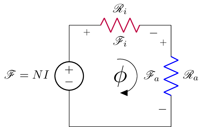
The code is a LaTeX document that generates an electrical circuit diagram using the circuitikz package. The circuit consists of a voltage source with a label $\mathscr{F}\equal NI$ and two resistors labeled $\mathscr{R}_i$ and $\mathscr{R}_a$, colored purple and blue respectively. The resistors are connected in series with the voltage source. Additionally, the code draws an arc with a label $\phi$ using the arc command. The final line of the code sets a label for the figure, but it is not used in the actual diagram.
Keywords
circuitikz, graphicx, mathrsfs, amssymb, amsmath, circuit, vector, resistor, voltage, node, label.
Source Code
\documentclass{standalone}
\usepackage[american]{circuitikz}
\usepackage{graphicx}
\usepackage{mathrsfs}
\usepackage{latexsym,amssymb,amsmath}
\newcommand{\equal}{=}
\begin{document}
	\begin{circuitikz}
		\draw (0,3) to [V,l_=$\mathscr{F}\equal NI$] (0,0)
		(0,3) to  [R, l^= $\mathscr{R}_{i}$,v_>=$\mathscr{F}_i$, color=purple] (3,3)
	    (3,0) -- (0,0)
	     (3,3) to [R, l^= $\mathscr{R}_{a}$,v_>=$\mathscr{F}_a$, color=blue] (3,0);

	      \draw[thin, <-, >=triangle 45] (1.5,1.5) node[scale=2]{$\phi$}   ++(-90:0.5) arc (-90:100:0.5);
      \end{circuitikz}
	\label{fig:q1fig}
\end{document}