Description
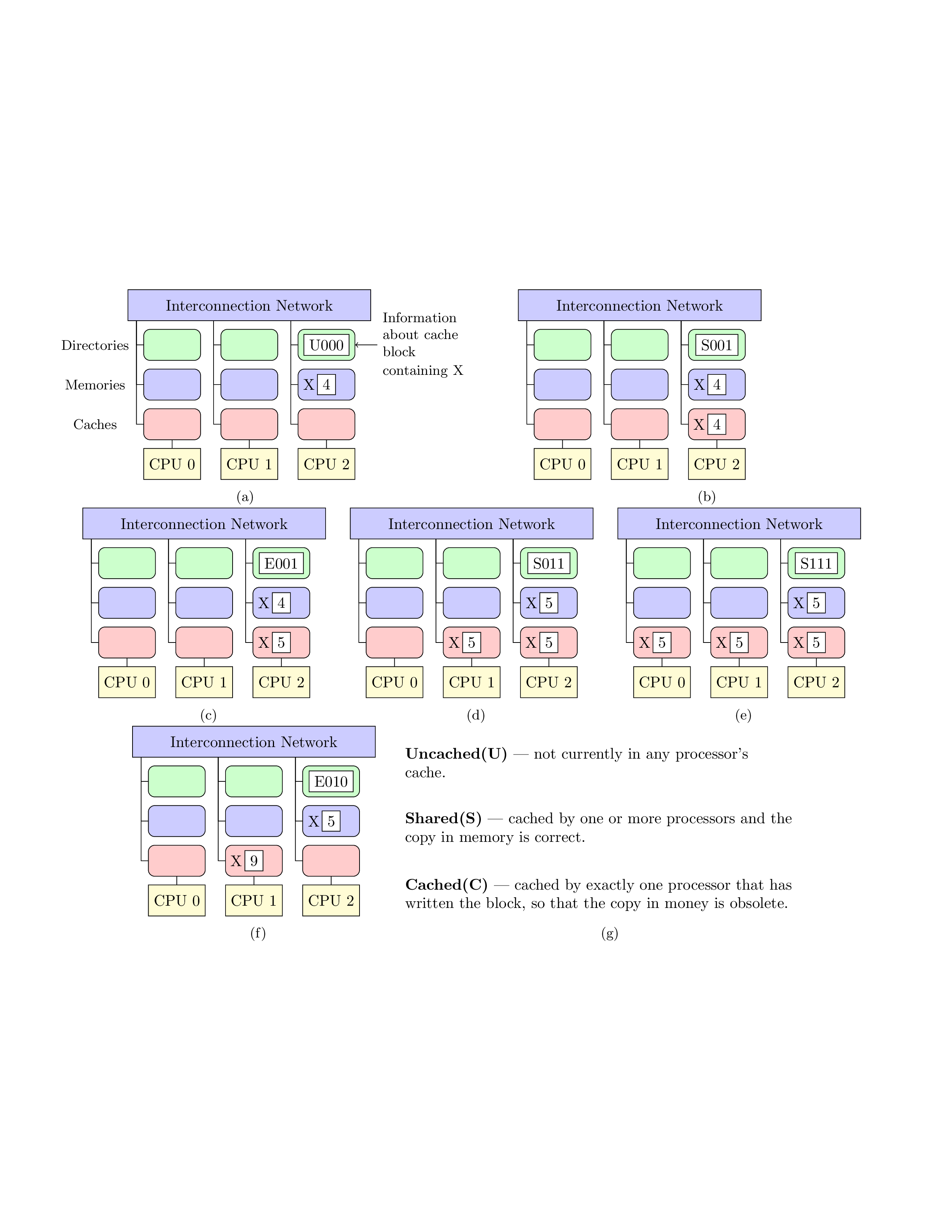
This code defines a diagram using TikZ package in LaTeX. The diagram represents a computer architecture where there are three CPUs (central processing units) connected to three caches, which in turn are connected to three directories and three memories. The CPUs, caches, directories, and memories are represented by rectangular nodes with different colors. The interconnection network is represented by a blue rectangle. The CPUs are labeled as CPU 0, CPU 1, and CPU 2. The caches are labeled as cache blocks containing data. The directories are labeled as U000. One cache block (labeled X) is connected to one of the memories.
The code defines different styles for the nodes such as intn, d, m, and ca. These styles are used to define the properties of the nodes, such as the shape, color, and size of the nodes. The nodes are positioned using the node distance and position options.
The code uses the subcaption package to create subfigures within a single figure environment. The code also uses the calc library of TikZ to calculate the positions of nodes relative to other nodes. The code also adds labels to some of the nodes to provide additional information. Finally, an arrow is added to connect a label outside the diagram to one of the nodes inside the diagram.
Keywords
tikzpicture, node, draw, rectangle, fill, text, below, of, align, center, minimum height, minimum width, anchor, east, west.
Source Code
\documentclass{article}
\usepackage[left=0.5in,right=0.5in,top=0in,bottom=0in]{geometry}
\usepackage{tikz}
\usetikzlibrary{shapes,arrows,shadows, positioning, calc}
% Define block styles used later

% Interconnection network block
\tikzstyle{intn}=[draw, fill=blue!20, text width=15em,
    text centered, minimum height=2em]

% Directory block
\tikzstyle{d} = [text width=3em, text centered, minimum height=2em,rounded corners,fill=green!20]
% memory block
\tikzstyle{m} = [text width=3em, align=left, minimum height=2em,rounded corners,fill=blue!20]

% Caches
\tikzstyle{ca} = [text width=3em, text centered, minimum height=2em,rounded corners, fill=red!20]

% CPU Blocks

\tikzstyle{cpu} = [text width=3em, text centered, minimum height=2em,fill=yellow!20]
\usepackage{subcaption}

\begin{document}
\begin{figure}
    \centering
    \begin{subfigure}[b]{0.45\textwidth}
            \begin{tikzpicture}[node distance=1.75cm and 1cm]
            % Block nodes
            \node (in1) [draw, intn] {Interconnection Network};
            \node (d2) [yshift=-0.9cm, draw, d] {};
            \node (d1) [left of = d2, draw, d] {};
            \node (d3) [right of = d2, draw, d] {};

            \node (m2) [yshift=-1.8cm, draw, m] {};
            \node (m1) [left of = m2, draw, m] {};
            \node (m3) [right of = m2, draw, m] {X};


            \node (ca2) [yshift=-2.7cm, draw, ca] {};
            \node (ca1) [left of = ca2, draw, ca] {};
            \node (ca3) [right of = ca2, draw, ca] {};

            \node (cpu2) [yshift=-3.6cm, draw, cpu] {CPU 1};
            \node (cpu1) [left of = cpu2,draw, cpu] {CPU 0};
            \node (cpu3) [right of = cpu2, draw, cpu] {CPU 2};

            % Node within nodes
            % Label inside node
            \node[draw,fill=white!30] at (d3.center) {U000};
            \node[draw,fill=white!30] at (m3.center) {4};
            % Label nodes, comment out for preceeding diagrams
            \node (dlabel) [left of = d1] {\small{Directories}};
            \node (mlabel) [left of = m1] {\small{Memories}};
            \node (calabel) [left of = ca1] {\small{Caches}};

            % Paths to connect all nodes for first column
            \draw ($(in1.south west) +(0.2,0)$) |- (d1.west);
            \draw  (m1.west) -| ($(in1.south west) +(0.2,0) $);
            \draw  (ca1.west) -| ($(in1.south west) +(0.2,0) $);

            % Paths for second column
            \draw ($(in1.south west) +(1.95,0)$) |- (d2.west);
            \draw  (m2.west) -| ($(in1.south west) +(1.95,0) $);
            \draw  (ca2.west) -| ($(in1.south west) +(1.95,0) $);

            % Paths for third column
            \draw ($(in1.south west) +(3.7,0)$) |- (d3.west);
            \draw  (m3.west) -| ($(in1.south west) +(3.7,0) $);
            \draw  (ca3.west) -| ($(in1.south west) +(3.7,0) $);

            % CPU Connections
            \draw (ca1) -- (cpu1);
            \draw (ca2) -- (cpu2);
            \draw (ca3) -- (cpu3);

            % arrow outside
            \node (ulabel) [right = 0.5cm of d3, text width=2cm] {\small{Information about cache block \\ containing X}};

            \draw [->] (ulabel) -- (d3.east);

            %\draw  (cpu1.west) -| ($(in1.south west) +(0.1,0) $);
            \end{tikzpicture}
            \caption{}
        \end{subfigure}
\hfill %add desired spacing between images, e. g. ~, \quad, \qquad, \hfill etc.
    %(or a blank line to force the subfigure onto a new line)
\begin{subfigure}[b]{0.45\textwidth}
\begin{tikzpicture}[node distance=1.75cm and 1cm]
% Block nodes
\node (in1) [draw, intn] {Interconnection Network};
\node (d2) [yshift=-0.9cm, draw, d] {};
\node (d1) [left of = d2, draw, d] {};
\node (d3) [right of = d2, draw, d] {};

\node (m2) [yshift=-1.8cm, draw, m] {};
\node (m1) [left of = m2, draw, m] {};
\node (m3) [right of = m2, draw, m] {X};


\node (ca2) [yshift=-2.7cm, draw, ca] {};
\node (ca1) [left of = ca2, draw, ca] {};
\node (ca3) [right of = ca2, draw, ca] {};

\node (cpu2) [yshift=-3.6cm, draw, cpu] {CPU 1};
\node (cpu1) [left of = cpu2,draw, cpu] {CPU 0};
\node (cpu3) [right of = cpu2, draw, cpu] {CPU 2};

% Node within nodes
% Label inside node
\node[draw,fill=white!30] at (d3.center) {S001};
\node[draw,fill=white!30] at (m3.center) {4};

\node[xshift=-0.4cm] at (ca3.center) {X};
\node[draw,fill=white!30] at (ca3.center) {4};
% Label nodes, comment out for preceeding diagrams
% \node (dlabel) [left of = d1] {\small{Directories}};
% \node (mlabel) [left of = m1] {\small{Memories}};
% \node (calabel) [left of = ca1] {\small{Caches}};

% Paths to connect all nodes for first column
\draw ($(in1.south west) +(0.2,0)$) |- (d1.west);
\draw  (m1.west) -| ($(in1.south west) +(0.2,0) $);
\draw  (ca1.west) -| ($(in1.south west) +(0.2,0) $);

% Paths for second column
\draw ($(in1.south west) +(1.95,0)$) |- (d2.west);
\draw  (m2.west) -| ($(in1.south west) +(1.95,0) $);
\draw  (ca2.west) -| ($(in1.south west) +(1.95,0) $);

% Paths for third column
\draw ($(in1.south west) +(3.7,0)$) |- (d3.west);
\draw  (m3.west) -| ($(in1.south west) +(3.7,0) $);
\draw  (ca3.west) -| ($(in1.south west) +(3.7,0) $);

% CPU Connections
\draw (ca1) -- (cpu1);
\draw (ca2) -- (cpu2);
\draw (ca3) -- (cpu3);

%\draw  (cpu1.west) -| ($(in1.south west) +(0.1,0) $);
\end{tikzpicture}
\caption{}
\end{subfigure}
% Row two
\begin{subfigure}[b]{0.3\textwidth}
\begin{tikzpicture}[node distance=1.75cm and 1cm]
% Block nodes
\node (in1) [draw, intn] {Interconnection Network};
\node (d2) [yshift=-0.9cm, draw, d] {};
\node (d1) [left of = d2, draw, d] {};
\node (d3) [right of = d2, draw, d] {};

\node (m2) [yshift=-1.8cm, draw, m] {};
\node (m1) [left of = m2, draw, m] {};
\node (m3) [right of = m2, draw, m] {X};


\node (ca2) [yshift=-2.7cm, draw, ca] {};
\node (ca1) [left of = ca2, draw, ca] {};
\node (ca3) [right of = ca2, draw, ca] {};

\node (cpu2) [yshift=-3.6cm, draw, cpu] {CPU 1};
\node (cpu1) [left of = cpu2,draw, cpu] {CPU 0};
\node (cpu3) [right of = cpu2, draw, cpu] {CPU 2};

% Node within nodes
% Label inside node
\node[draw,fill=white!30] at (d3.center) {E001};
\node[draw,fill=white!30] at (m3.center) {4};

\node[xshift=-0.4cm] at (ca3.center) {X};
\node[draw,fill=white!30] at (ca3.center) {5};
% Label nodes, comment out for preceeding diagrams
% \node (dlabel) [left of = d1] {\small{Directories}};
% \node (mlabel) [left of = m1] {\small{Memories}};
% \node (calabel) [left of = ca1] {\small{Caches}};

% Paths to connect all nodes for first column
\draw ($(in1.south west) +(0.2,0)$) |- (d1.west);
\draw  (m1.west) -| ($(in1.south west) +(0.2,0) $);
\draw  (ca1.west) -| ($(in1.south west) +(0.2,0) $);

% Paths for second column
\draw ($(in1.south west) +(1.95,0)$) |- (d2.west);
\draw  (m2.west) -| ($(in1.south west) +(1.95,0) $);
\draw  (ca2.west) -| ($(in1.south west) +(1.95,0) $);

% Paths for third column
\draw ($(in1.south west) +(3.7,0)$) |- (d3.west);
\draw  (m3.west) -| ($(in1.south west) +(3.7,0) $);
\draw  (ca3.west) -| ($(in1.south west) +(3.7,0) $);

% CPU Connections
\draw (ca1) -- (cpu1);
\draw (ca2) -- (cpu2);
\draw (ca3) -- (cpu3);

%\draw  (cpu1.west) -| ($(in1.south west) +(0.1,0) $);
\end{tikzpicture}
\caption{}
\end{subfigure}
~ %add desired spacing between images, e. g. ~, \quad, \qquad, \hfill etc.
    %(or a blank line to force the subfigure onto a new line), object d
\begin{subfigure}[b]{0.3\textwidth}
\begin{tikzpicture}[node distance=1.75cm and 1cm]
% Block nodes
\node (in1) [draw, intn] {Interconnection Network};
\node (d2) [yshift=-0.9cm, draw, d] {};
\node (d1) [left of = d2, draw, d] {};
\node (d3) [right of = d2, draw, d] {};

\node (m2) [yshift=-1.8cm, draw, m] {};
\node (m1) [left of = m2, draw, m] {};
\node (m3) [right of = m2, draw, m] {X};


\node (ca2) [yshift=-2.7cm, draw, ca] {};
\node (ca1) [left of = ca2, draw, ca] {};
\node (ca3) [right of = ca2, draw, ca] {};

\node (cpu2) [yshift=-3.6cm, draw, cpu] {CPU 1};
\node (cpu1) [left of = cpu2,draw, cpu] {CPU 0};
\node (cpu3) [right of = cpu2, draw, cpu] {CPU 2};

% Node within nodes
% Label inside node
\node[draw,fill=white!30] at (d3.center) {S011};
\node[draw,fill=white!30] at (m3.center) {5};

\node[xshift=-0.4cm] at (ca2.center) {X};
\node[draw,fill=white!30] at (ca2.center) {5};

\node[xshift=-0.4cm] at (ca3.center) {X};
\node[draw,fill=white!30] at (ca3.center) {5};
% Label nodes, comment out for preceeding diagrams
% \node (dlabel) [left of = d1] {\small{Directories}};
% \node (mlabel) [left of = m1] {\small{Memories}};
% \node (calabel) [left of = ca1] {\small{Caches}};

% Paths to connect all nodes for first column
\draw ($(in1.south west) +(0.2,0)$) |- (d1.west);
\draw  (m1.west) -| ($(in1.south west) +(0.2,0) $);
\draw  (ca1.west) -| ($(in1.south west) +(0.2,0) $);

% Paths for second column
\draw ($(in1.south west) +(1.95,0)$) |- (d2.west);
\draw  (m2.west) -| ($(in1.south west) +(1.95,0) $);
\draw  (ca2.west) -| ($(in1.south west) +(1.95,0) $);

% Paths for third column
\draw ($(in1.south west) +(3.7,0)$) |- (d3.west);
\draw  (m3.west) -| ($(in1.south west) +(3.7,0) $);
\draw  (ca3.west) -| ($(in1.south west) +(3.7,0) $);

% CPU Connections
\draw (ca1) -- (cpu1);
\draw (ca2) -- (cpu2);
\draw (ca3) -- (cpu3);

%\draw  (cpu1.west) -| ($(in1.south west) +(0.1,0) $);
\end{tikzpicture}
\caption{}
\end{subfigure}
~
\begin{subfigure}[b]{0.3\textwidth}
\begin{tikzpicture}[node distance=1.75cm and 1cm]
% Block nodes
\node (in1) [draw, intn] {Interconnection Network};
\node (d2) [yshift=-0.9cm, draw, d] {};
\node (d1) [left of = d2, draw, d] {};
\node (d3) [right of = d2, draw, d] {};

\node (m2) [yshift=-1.8cm, draw, m] {};
\node (m1) [left of = m2, draw, m] {};
\node (m3) [right of = m2, draw, m] {X};


\node (ca2) [yshift=-2.7cm, draw, ca] {};
\node (ca1) [left of = ca2, draw, ca] {};
\node (ca3) [right of = ca2, draw, ca] {};

\node (cpu2) [yshift=-3.6cm, draw, cpu] {CPU 1};
\node (cpu1) [left of = cpu2,draw, cpu] {CPU 0};
\node (cpu3) [right of = cpu2, draw, cpu] {CPU 2};

% Node within nodes
% Label inside node
\node[draw,fill=white!30] at (d3.center) {S111};
\node[draw,fill=white!30] at (m3.center) {5};

\node[xshift=-0.4cm] at (ca1.center) {X};
\node[draw,fill=white!30] at (ca1.center) {5};

\node[xshift=-0.4cm] at (ca2.center) {X};
\node[draw,fill=white!30] at (ca2.center) {5};

\node[xshift=-0.4cm] at (ca3.center) {X};
\node[draw,fill=white!30] at (ca3.center) {5};
% Label nodes, comment out for preceeding diagrams
% \node (dlabel) [left of = d1] {\small{Directories}};
% \node (mlabel) [left of = m1] {\small{Memories}};
% \node (calabel) [left of = ca1] {\small{Caches}};

% Paths to connect all nodes for first column
\draw ($(in1.south west) +(0.2,0)$) |- (d1.west);
\draw  (m1.west) -| ($(in1.south west) +(0.2,0) $);
\draw  (ca1.west) -| ($(in1.south west) +(0.2,0) $);

% Paths for second column
\draw ($(in1.south west) +(1.95,0)$) |- (d2.west);
\draw  (m2.west) -| ($(in1.south west) +(1.95,0) $);
\draw  (ca2.west) -| ($(in1.south west) +(1.95,0) $);

% Paths for third column
\draw ($(in1.south west) +(3.7,0)$) |- (d3.west);
\draw  (m3.west) -| ($(in1.south west) +(3.7,0) $);
\draw  (ca3.west) -| ($(in1.south west) +(3.7,0) $);

% CPU Connections
\draw (ca1) -- (cpu1);
\draw (ca2) -- (cpu2);
\draw (ca3) -- (cpu3);

%\draw  (cpu1.west) -| ($(in1.south west) +(0.1,0) $);
\end{tikzpicture}
\caption{}
\end{subfigure}
% Row 3
\begin{subfigure}[b]{0.3\textwidth}
\begin{tikzpicture}[node distance=1.75cm and 1cm]
% Block nodes
\node (in1) [draw, intn] {Interconnection Network};
\node (d2) [yshift=-0.9cm, draw, d] {};
\node (d1) [left of = d2, draw, d] {};
\node (d3) [right of = d2, draw, d] {};

\node (m2) [yshift=-1.8cm, draw, m] {};
\node (m1) [left of = m2, draw, m] {};
\node (m3) [right of = m2, draw, m] {X};


\node (ca2) [yshift=-2.7cm, draw, ca] {};
\node (ca1) [left of = ca2, draw, ca] {};
\node (ca3) [right of = ca2, draw, ca] {};

\node (cpu2) [yshift=-3.6cm, draw, cpu] {CPU 1};
\node (cpu1) [left of = cpu2,draw, cpu] {CPU 0};
\node (cpu3) [right of = cpu2, draw, cpu] {CPU 2};

% Node within nodes
% Label inside node
\node[draw,fill=white!30] at (d3.center) {E010};
\node[draw,fill=white!30] at (m3.center) {5};

\node[xshift=-0.4cm] at (ca2.center) {X};
\node[draw,fill=white!30] at (ca2.center) {9};

% Label nodes, comment out for preceeding diagrams
% \node (dlabel) [left of = d1] {\small{Directories}};
% \node (mlabel) [left of = m1] {\small{Memories}};
% \node (calabel) [left of = ca1] {\small{Caches}};

% Paths to connect all nodes for first column
\draw ($(in1.south west) +(0.2,0)$) |- (d1.west);
\draw  (m1.west) -| ($(in1.south west) +(0.2,0) $);
\draw  (ca1.west) -| ($(in1.south west) +(0.2,0) $);

% Paths for second column
\draw ($(in1.south west) +(1.95,0)$) |- (d2.west);
\draw  (m2.west) -| ($(in1.south west) +(1.95,0) $);
\draw  (ca2.west) -| ($(in1.south west) +(1.95,0) $);

% Paths for third column
\draw ($(in1.south west) +(3.7,0)$) |- (d3.west);
\draw  (m3.west) -| ($(in1.south west) +(3.7,0) $);
\draw  (ca3.west) -| ($(in1.south west) +(3.7,0) $);

% CPU Connections
\draw (ca1) -- (cpu1);
\draw (ca2) -- (cpu2);
\draw (ca3) -- (cpu3);

%\draw  (cpu1.west) -| ($(in1.south west) +(0.1,0) $);
\end{tikzpicture}
\caption{}
\end{subfigure}
~
\begin{subfigure}[b]{0.5\textwidth}
\begin{tikzpicture}[node distance=1.5cm and 1cm]
\node[text width=25 em] (u){\textbf{Uncached(U)} --- not currently in any processor's cache.};
\node[text width=25 em, below of = u ] (s) {\textbf{Shared(S)} --- cached by one or more processors and the copy in memory is correct.};
\node[text width=25 em, below of = s ] {\textbf{Cached(C)} --- cached by exactly one processor that has written the block, so that the copy in money is obsolete.};
\end{tikzpicture}
\caption{}
\end{subfigure}
%\caption*{Directory-based Cache Operations. (a) Starting Cache from Figure 2.19. (b) State after CPU 2 reads X. (c) State after CPU 2 writes value 5 to X. (d) State after CPU 1 reads X. (e) State after CPU 0 reads X. (f) State after CPU 1 writes value 9 to X.}
\end{figure}
\end{document}