Description
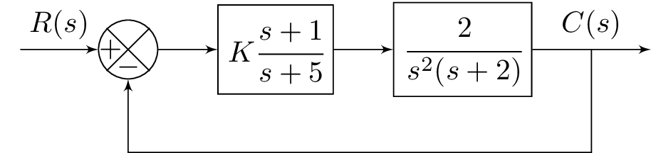
The code above creates a block diagram using the TikZ package in LaTeX. The diagram includes several components, including an input node labeled "A", a computation node labeled "B", a block node labeled "C" with the transfer function , another block node labeled "D" with the transfer function , and an output node labeled "E". There are also several links between these components, including a link labeled "" from node A to node B, a link from node B to node C, a link from node C to node D, and a link labeled "" from node D to node E. Finally, there is a return link from the output node E to the computation node B.
Keywords
amsmath, amssymb, blox, tikz, Input, Comp, Link, Bloc, Output, Return.
Source Code
\documentclass{standalone}
\usepackage{amsmath}  % For math
\usepackage{amssymb}  % For more math

\usepackage{blox}
\usepackage{tikz}
\begin{document}
\begin{tikzpicture}
\bXInput{A}
\bXComp{B}{A}
\bXLink[$R(s)$]{A}{B}
\bXBloc[2]{C}{$K\cfrac{s+1}{s+5}$}{B}
%\bXLink[$V_1$]{B}{C}
\bXLink{B}{C}
\bXBloc[2]{D}{$\cfrac{2}{s^2(s+2)}$}{C}
\bXLink{C}{D}
\bXOutput[4]{E}{D}
\bXLink[$C(s)$]{D}{E}
\bXReturn{D-E}{B}{}
\end{tikzpicture}

\end{document}