Description
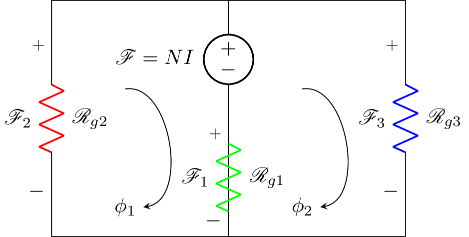
This code generates an electrical circuit diagram using the circuitikz package. The circuit diagram has three resistors, labeled , , and , and three voltage sources labeled , , and . The resistors and voltage sources are arranged in a circuit such that is connected to , which is connected to , which is connected to , which is connected to , which is connected to . The circuit is completed by connecting to and connecting to . Additionally, the diagram has two labels for the phase angles, and , which are connected to the circuit using curved arrows.
Keywords
latex, circuitikz, graphicx, mathrsfs, latexsym, amssymb, amsmath, documentclass, newcommand, standalone, draw, V, R, node, color, l, to, bent, equal, phi.
Source Code
\documentclass{standalone}
\usepackage[american]{circuitikz}
\usepackage{graphicx}
\usepackage{mathrsfs}
\usepackage{latexsym,amssymb,amsmath}
\newcommand{\equal}{=}
\begin{document}
		\begin{circuitikz}
			\draw (3,4) to [V,l_=$\mathscr{F}\equal NI$] (3,2)
			(3,2) to [R,l^=$\mathscr{R}_{g1}$, v_>=$\mathscr{F}_1$, color=green] (3,0)
			(3,2) -- (3,0)
			(3,0) -- (0,0)
			(0,4) to [R,l^=$\mathscr{R}_{g2}$, v_>=$\mathscr{F}_2$, color=red] (0,0)
			(6,4) to [R, l^=$\mathscr{R}_{g3}$,v_>=$\mathscr{F}_3$, color=blue] (6,0)
			(6,0) -- (3,0)
			(0,4) -- (6,4);
			%	     \draw[thin, <-, >=triangle 45] (1.5,1.5) node[scale=2]{$\phi$}   ++(-90:0.5) arc (-90:100:0.5);
			\node (phi) at (1.25,0.5) {$\phi_1$};
			\draw[-stealth]  (1.25,2.5) to [bend left=90] (phi);

			\node (phi) at (4.25,0.5) {$\phi_2$};
			\draw[-stealth]  (4.25,2.5) to [bend left=90] (phi);
			\end{circuitikz}
%	\begin{circuitikz}
%		\draw (0,3) to [V,l_=$\mathscr{F}\equal NI$] (0,0)
%		(0,3) to [R,l^=$\mathscr{R}_{1,thick}$, v_>=$\mathscr{F}_1$, color=red] (0,6)
%		(0,6) to [R, l^=$\mathscr{R}_{2,thin}$,v_>=$\mathscr{F}_2$, color=blue] (3,6)
%		(3,6) -- (3,3)
%	    (3,3) to [R, l^=$\mathscr{R}_{3,thick}$,v_>=$\mathscr{F}_3$, color=red] (3,0)
%	     (3,0) to [R, l^= $\mathscr{R}_{4,thin}$,v_>=$\mathscr{F}_4$, color=blue] (0,0)
%
%	     (1.5,3) node[scale=4]{${\circlearrowright}$}
%	     (1.5,3) node[scale=2]{${\mathbf{\phi}}$};
%		;\end{circuitikz}
%	\label{fig:q1fig}
\end{document}