Description
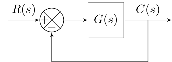
The code above creates a block diagram using the TikZ package. It defines several block components using the "blox" package, including an input (labeled "A"), a computation block (labeled "B"), a block for a transfer function with the label "G(s)", an output block (labeled "E"), and a return block. It connects these blocks with arrows labeled with either transfer functions or block names. The diagram represents a feedback control system with an input labeled "R(s)", a transfer function "G(s)", and an output labeled "C(s)". The return block connects the output of the system back to the input of the computation block, forming a closed loop.
Keywords
amsmath, amssymb, blox, tikz, tikzpicture, bXInput, bXComp, bXLink, bXBloc, bXOutput, bXReturn.
Source Code
\documentclass{standalone}
\usepackage{amsmath}  % For math
\usepackage{amssymb}  % For more math

\usepackage{blox}
\usepackage{tikz}
\begin{document}
\begin{tikzpicture}
\bXInput{A}
\bXComp{B}{A}
\bXLink[$R(s)$]{A}{B}
\bXBloc[2]{C}{$\displaystyle G(s)$}{B}
\bXLink{B}{C}
\bXOutput[4]{E}{C}
\bXLink[$C(s)$]{C}{E}
\bXReturn{C-E}{B}{}
\end{tikzpicture}

\end{document}