Description
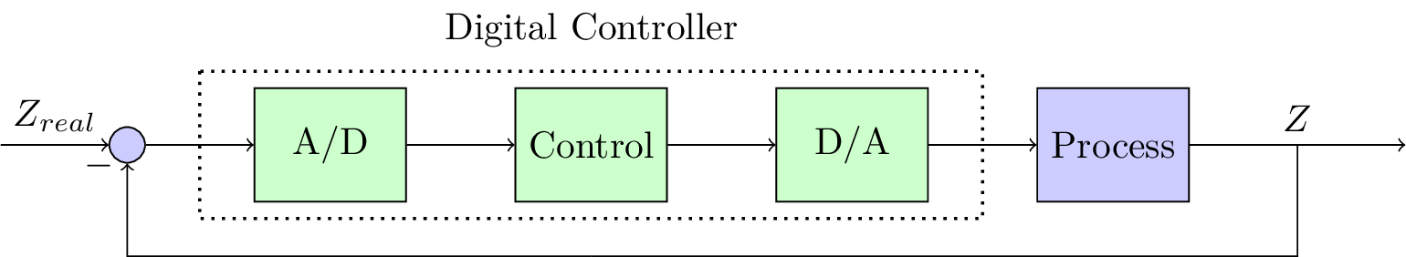
The code is a LaTeX document that generates a block diagram using the TikZ package. The diagram represents a digital control system consisting of an analog-to-digital converter (A/D), a digital controller, a digital-to-analog converter (D/A), and a process block.
The diagram contains several predefined styles for the various blocks, including "block," "controller," "sum," "input," and "output." The "block" and "controller" styles have different fill colors, blue and green respectively, and have a minimum height and width.
The diagram is made up of several nodes, including the input and output nodes, as well as nodes for the summing junction, A/D, digital controller, D/A, and process block. The nodes are connected using arrows, with labels indicating the information flow between each block.
The diagram also includes a rectangle drawn around the digital controller and D/A nodes using the "thick,dotted" style. This is used to group the digital components together as a single entity.
Finally, the diagram includes several positioning nodes using the TikZ library, such as "right" and "below," to position the nodes and labels in the correct location relative to one another.
Keywords
TikZ, nodes, input, output, arrows, controller, sum, block, positioning, shapes, dotted, rectangle.
Source Code
\documentclass[tikz]{standalone}
\usepackage{amsmath,amssymb}
\usepackage{graphicx} % Required for inserting images
\usepackage{booktabs}
\usepackage{tabularx}
\usepackage{circuitikz}

\usetikzlibrary{positioning}
\usetikzlibrary{shapes,arrows}
\tikzstyle{block} = [draw, fill=blue!20, rectangle, minimum height=3em, minimum width=4em]
\tikzstyle{controller} = [draw, fill=green!20, rectangle, minimum height=3em, minimum width=4em]
\tikzstyle{sum} = [draw, fill=blue!20, circle, node distance=1cm]
\tikzstyle{input} = [coordinate]
\tikzstyle{output} = [coordinate]
\begin{document}
\begin{tikzpicture}[auto]
% Nodes
\node [input] (input) {};
\node [sum, right = 1cm of input] (sum) {};
\node [controller, right = 1cm of sum] (con1) {A/D};
\node [controller, right = 1cm of con1] (con2) {Control};
\node [controller, right = 1cm of con2] (system2) {D/A};
\node [block, right = 1cm of system2] (system3) {Process};
\node [output, right = 2cm of system3] (output) {};
\node [input, below = 0.5cm of con2] (m) {};
% Arrows
\draw [draw,->] (input) -- node {$Z_{real}$} (sum);
\draw [->] (sum) -- (con1);
\draw [->] (con1) -- (con2);
\draw [->] (con2) -- node {$$} (system2);
\draw [->] (system2) -- node {$$} (system3);
\draw [->] (system3) -- node (y) {$Z$}(output);
\draw [-] (y) |- (m) {} ;
\draw [->] (m) -| node[pos=0.99] {$-$}  node [near end] {} (sum);
\draw[thick,dotted]     ($(con1.north west)+(-0.5,0.15)$) rectangle ($(system2.south east)+(0.5,-0.15)$);
\node [above = 0.25cm of con2] {Digital Controller};
%\node [above = of near end] {+};
\end{tikzpicture}
\end{document}