Description
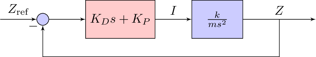
The LaTeX code defines a diagram of a control system using the TikZ package. The diagram consists of several nodes representing different components of the control system and arrows connecting the nodes to show the flow of signals. The components include an input, a summing point, a controller, a block, and an output. The controller is represented by a rectangle with the label "K_D s + K_P" and the block is represented by a rectangle with the label "k/ms^2". The input and output are represented by coordinate nodes, and the summing point is represented by a circle with the label "+". The diagram also includes a node below the controller labeled "m". The arrows show the flow of signals from the input to the output, passing through the summing point, the controller, and the block. The arrow from the output is split to connect to the node labeled "m" and the summing point, indicating feedback.
Keywords
TikZ, positioning, shapes, arrows, circuitikz, nodes, input, output, sum, block, controller, arrows.
Source Code
\documentclass{standalone}
\usepackage{graphicx} % Required for inserting images
\usepackage{tikz}
\usetikzlibrary{positioning}
\usetikzlibrary{shapes,arrows}
\newcommand{\sse}{\mathrm{ss}}
\newcommand{\re}{\mathrm{ref}}
\usepackage{amsmath, amsthm}
\usepackage{booktabs}
\usepackage{tabularx}
\usepackage{circuitikz}
\tikzstyle{block} = [draw, fill=blue!20, rectangle, minimum height=3em, minimum width=4em]
\tikzstyle{controller} = [draw, fill=red!20, rectangle, minimum height=3em, minimum width=4em]
\tikzstyle{sum} = [draw, fill=blue!20, circle, node distance=1cm]
\tikzstyle{input} = [coordinate]
\tikzstyle{output} = [coordinate]

\begin{document}
    \begin{tikzpicture}[auto, >=latex']
        % Nodes
        \node [input] (input) {};
        \node [sum, right = 1cm of input] (sum) {};
        \node [controller, right = 1cm of sum] (system) {$K_D s + K_P$};
        \node [block, right = 1cm of system] (system2) {$\frac{k}{ms^2}$};
        \node [output, right = 2cm of system2] (output) {};
        \node [input, below = 0.5cm of system] (m) {};
        % Arrows
        \draw [draw,->] (input) -- node {$Z_\re$} (sum);
        \draw [->] (sum) -- node {} (system);
        \draw [->] (system) -- node {$I$} (system2);
        \draw [->] (system2) -- node (y) {$Z$}(output);
        \draw [-] (y) |- (m) {} ;
        \draw [->] (m) -| node[pos=0.99] {$-$}  node [near end] {} (sum);
    \end{tikzpicture}
    % \end{lateximage}% NEW
    % \caption{Proportional-derivative control.}
\end{document}