Description
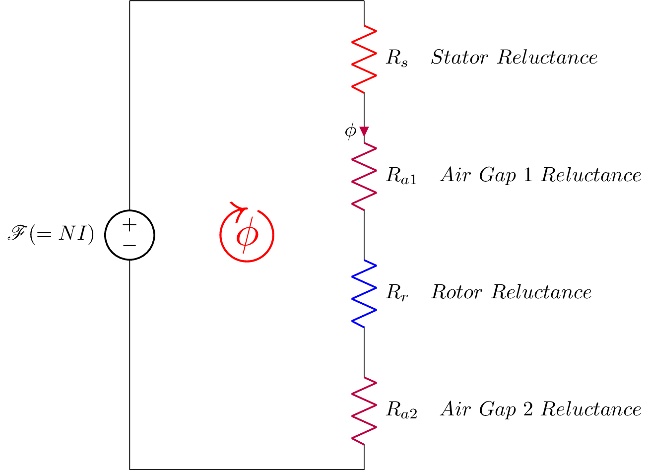
This is a LaTeX document that includes several packages such as circuitikz, graphicx, mathrsfs, latexsym, amssymb, and amsmath. The code creates an electrical circuit diagram using the circuitikz package. The circuit consists of a voltage source labeled with the symbol for magnetic flux density () connected to a series of resistors labeled with different reluctances (, , , and ). The resistors are colored with different colors such as purple, blue, and red to differentiate them. There is a current flowing through the circuit represented by the symbol for magnetic flux (). The code also includes a circle with an arrow (in red color) to indicate the direction of rotation of the magnetic field ().
Keywords
circuit, circuitikz, voltage source, resistance, rotor, stator, air gap, reluctance, colors, red, purple, blue, phi, symbol.
Source Code
\documentclass{standalone}
\usepackage{circuitikz}
\usepackage{graphicx}
\usepackage{mathrsfs}
\usepackage{latexsym,amssymb,amsmath}
\newcommand{\equal}{=}
\begin{document}

	\begin{circuitikz}[american voltages,scale =1]
		\draw (0,8) to [voltage source,l_=$\mathscr{F}(\equal NI)$] (0,0) -- (4,0)
		%node[anchor=south] {$v_L$}
		to [R, l_= $R_{a2} \quad Air \ Gap \ 2 \ Reluctance $,color=purple] (4,2)
		to [R, l_= $R_{r} \quad Rotor \ Reluctance $,color=blue] (4,4)
		to [R,i^<=$\phi$, l_= $R_{a1} \quad Air \ Gap \ 1 \ Reluctance $,color=purple] (4,6)
		to [R, l_= $R_{s} \quad Stator \ Reluctance $,color=red] (4,8)
		(4,8) -- (0,8)
		%(2,3) -- (4,3) to [L=$L$, i>^=$i_L(t)$, v=$v_L(t)$] (4,0) -- (0,0)
		(2,4) node[scale=4]{$\textcolor{red}{\circlearrowright}$}
		(2,4) node[scale=2]{$\textcolor{red}{\mathbf{\phi}}$};
		;\end{circuitikz}
\end{document}