Description
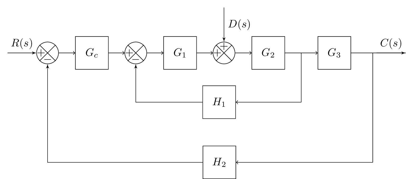
The code above is a LaTeX document that creates a block diagram using the blox and tikz packages. The diagram consists of several blocks and links that represent a control system with feedback. The blocks represent various transfer functions (Gc, G1, G2, G3, H1, and H2), while the links represent signals or variables (R(s), D(s), C(s), and the output). The code also includes various tikz styles and libraries for drawing the diagram elements, such as the connect style for drawing curved links over a block, and the tkz-euclide library for drawing geometric elements such as angles and circles.
Keywords
documentclass, standalone, blox, tikz, positioning, newcommand, equal, intersections, tkz-euclide, tikzset, connect, insert path, let, veclen, atan2, abs, in, arc, bXInput, input, bXComp, adder1, bXLink, R(s), bXBloc, Gc, adder2, G1, bXSuma, adder3, G2, bXBranchy, adder3up3, D(s), bXBranchx, G2Right15, G3, G3Right15, G2Right15Down3, H1, outputDown10, H2, bXOutput, end, draw, arrow, dash.
Source Code
\documentclass{standalone}

\usepackage{blox}
\usepackage{tikz}
\usetikzlibrary{positioning}
\newcommand{\equal}{=}
\usepackage{tikz}
\usetikzlibrary{intersections}
\usepackage{tkz-euclide}
% Radius for arc over intersection
\def\radius{1.mm}

\tikzset{
	connect/.style args={(#1) to (#2) over (#3) by #4}{
		insert path={
			let \p1=($(#1)-(#3)$), \n1={veclen(\x1,\y1)},
			\n2={atan2(\y1,\x1)}, \n3={abs(#4)}, \n4={#4>0 ?180:-180}  in
			(#1) -- ($(#1)!\n1-\n3!(#3)$)
			arc (\n2:\n2+\n4:\n3) -- (#2)
		}
	},
}

\begin{document}
\begin{tikzpicture}
\bXInput{input}				% Input
\bXComp{adder1}{input}			% First adder
\bXLink[$R(s)$]{input}{adder1}	% Input Label
\bXBloc[1.5]{Gc}{$G_c$}{adder1}			%BLock Gc
\bXComp{adder2}{Gc}		% second adder
\bXBloc[1.5]{G1}{$G_1$}{adder2}	% G1 Block
\bXSuma{adder3}{G1}			% third adder --suma variant
\bXBloc[1.5]{G2}{$G_2$}{adder3}	% G2 Block
\bXBranchy[-4.5]{adder3}{adder3up3} % adder3 up 3 units
\bXLink[$D(s)$]{adder3up3}{adder3}

\bXBranchx[3]{G2}{G2Right15}		% Right of G2 1.5 units
\bXBloc[1.5]{G3}{$G_3$}{G2Right15}		% G3 Block
\bXBranchx[3.5]{G3}{G3Right15}		% Right of G3 1.5 units
\bXBranchy[4.5]{G2Right15}{G2Right15Down3}	% Right from G2 1.5 units right and 3 units down
\bXBloc[-9]{H1}{$H_1$}{G2Right15Down3}	% H1 Block
\bXBranchy[10]{G3Right15}{outputDown10}

\bXBloc[-15.5]{H2}{$H_2$}{outputDown10}
\bXOutput[3]{end}{G3Right15}

%%Drawing most of the connecters here
\draw[->] (adder1) -- (Gc);
\draw[->] (Gc) -- (adder2);
\draw[->] (adder2) -- (G1);
\draw[->] (G1)  -- (adder3);
\draw[->] (adder3) -- (G2);
\draw[-] (G3) -- (end);
\draw[-] (G2Right15.center) -- (G2Right15Down3.center);
\draw[-] (G3Right15.center) -- (outputDown10.center);
\draw[->] (outputDown10.center) -- (H2);
\draw[->] (G2) -- (G3); % Connect G2 and G3
\draw[->] (G2Right15Down3.center)  -- (H1);

\bXLinkxy{H2}{adder1}
\bXLink[$C(s)$]{G3Right15}{end}	% Output Label
\bXLinkxy{H1}{adder2}
\end{tikzpicture}
\end{document}