Description
The code is a LaTeX document containing a tikzpicture environment that creates a diagram of a computer system architecture. The diagram is made up of various shapes and arrows, which are defined using the TikZ library.
The shapes used in the diagram include BlockCPU and BlockAltre rectangles, Periferic ellipses, and Registre and RegistreBuit rectangles. The Bus style is used to draw arrows representing buses in the architecture.
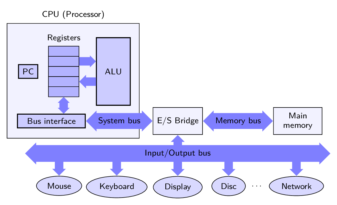
The diagram represents a computer system architecture, with a CPU (central processing unit) block at the center, surrounded by various other blocks and buses. The CPU block has an interface block, registers, a program counter (PC), and an arithmetic logic unit (ALU).
The buses in the architecture include a system bus, an input/output (I/O) bus, and a memory bus. The I/O bus is connected to various peripheral blocks, including a mouse and a keyboard. The memory bus is connected to the main memory block.
The diagram also includes labels and annotations to help explain the various components of the architecture.
Keywords
tikz, node, draw, rectangle, below, right, left, of, edge, fill, coordinate, text, font, style, path.
Source Code
\documentclass[tikz, border=2mm]{standalone}

\usetikzlibrary{positioning,shapes,arrows,backgrounds,external,fit,calc}
\usepackage[T1]{fontenc}
\usepackage[utf8]{inputenc}
\usepackage{lmodern}

\tikzset{
    BlockCPU/.style={draw,thick, fill=blue!20, rectangle},
    BlockAltre/.style={draw,thick, fill=blue!35, rectangle},
    Periferic/.style={ellipse, draw, fill=blue!15},
    Registre/.style={rectangle, draw, fill=blue!5},
    RegistreBuit/.style={rectangle, draw, fill=blue!30,minimum width=.9cm, minimum height=3mm, inner sep =0pt, outer sep=0.pt, anchor=south east},
    Bus/.style={fill=blue!50},
    Nom/.style={font=\normalsize\sffamily,text centered, minimum size=1cm, text width=1.5cm}
    }

\begin{document}
\begin{tikzpicture}[font={\sffamily\scriptsize}]

\node[Registre, minimum width=3.9cm, minimum height=3.4cm, anchor=south west, label={above:CPU (Processor)}] (CPU) at (0,0) {};
%\node[Nom,above right, align=left] (CPUnom) at (CPU.north west) {CPU};
\node[BlockCPU, minimum width=2cm, anchor=south west] (IB) at (0.3,0.3) {Bus interface};
\node[RegistreBuit] (Reg1) at ($(IB.north east)+(-2mm,5mm)$) {};
\node[RegistreBuit] (Reg2) at (Reg1.north east) {};
\node[RegistreBuit] (Reg3) at (Reg2.north east) {};
\node[RegistreBuit] (Reg4) at (Reg3.north east) {};
\node[RegistreBuit,label={above:Registers}] (Reg5) at (Reg4.north east) {};
\node[BlockCPU, left=3mm of Reg3] (PC) {PC};
\node[BlockCPU, right=5mm of Reg3, minimum width=1cm, minimum height=2cm] (ALU) {ALU};

\draw let \p1=($(Reg1.south) - (Reg1|-IB.north)$), \n1={veclen(\x1,\y1)} in node[double arrow, Bus, shape border rotate=90,anchor=north, minimum height=\n1-\pgflinewidth,minimum width=1mm, double arrow head extend=.5mm]  at ([yshift=.5\pgflinewidth]Reg1.south) {};

\node[single arrow, Bus, anchor=west, minimum width=2mm, single arrow head extend=.5mm, minimum height=5mm-.5\pgflinewidth] at (Reg4.east) {};

\node[single arrow, Bus, anchor=west, minimum width=2mm, single arrow head extend=.75mm, minimum height=5mm-.5\pgflinewidth, shape border rotate=180] at (Reg2.east) {};

\node[double arrow, Bus,, anchor=west, minimum width=1mm, double arrow head extend=.75mm] (BusS) at (IB.east) {System bus};

\node[Registre,minimum width=12mm,minimum height=8mm, anchor=west] (ES) at (BusS.east) {E/S Bridge};

\node[double arrow, Bus,, anchor=west, minimum width=1mm, double arrow head extend=.75mm] (BusM) at (ES.east) {Memory bus};

\node[Registre,minimum width=12mm,minimum height=8mm, text centered,text width=12mm,anchor=west] (Mem) at (BusM.east) {Main memory};

\node[double arrow, Bus,, anchor=north, minimum height=9cm, minimum width=2mm, double arrow head extend=.75mm,anchor=north] (BusES) at ([yshift=-.3cm]ES.south) {Input/Output bus};

\node[single arrow, Bus,, anchor=north, minimum width=2mm, single arrow head extend=.75mm, minimum height=3mm-.5\pgflinewidth, shape border rotate=90] (BusESP) at (ES.south) {};

\node[single arrow, Bus,, anchor=north, minimum width=2mm, single arrow head extend=.75mm, minimum height=5mm-.5\pgflinewidth, shape border rotate=270] (Per1) at ([shift={(-3.5cm,1mm)}]BusES.south) {};

\node[Periferic,anchor=north] (Ratoli) at (Per1.south) {Mouse};

\node[single arrow, Bus, anchor=north, minimum width=2mm, single arrow head extend=.75mm, minimum height=5mm-.5\pgflinewidth, shape border rotate=270] (Per2) at ([shift={(-1.8cm,1mm)}]BusES.south) {};

\node[Periferic,anchor=north] (Teclat) at (Per2.south) {Keyboard};

\node[single arrow, Bus,, anchor=north, minimum width=2mm, single arrow head extend=.75mm, minimum height=5mm, shape border rotate=270] (Per3) at ([shift={(0cm,1mm)}]BusES.south) {};

\node[Periferic,anchor=north] (Pantalla) at (Per3.south) {Display};

\node[single arrow, Bus,, anchor=north, minimum width=2mm, single arrow head extend=.75mm, minimum height=5mm, shape border rotate=270] (Per4) at ([shift={(1.5cm,1mm)}]BusES.south) {};

\node[Periferic,anchor=north] (Disc) at (Per4.south) {Disc};

\node[single arrow, Bus,, anchor=north, minimum width=2mm, single arrow head extend=.75mm, minimum height=5mm, shape border rotate=270] (Per5) at ([shift={(3.5cm,1mm)}]BusES.south) {};

\node[Periferic,anchor=north] (Xarxa) at (Per5.south) {Network};

\path (Disc) -- node {\dots} (Xarxa);

\end{tikzpicture}
\end{document}