Description
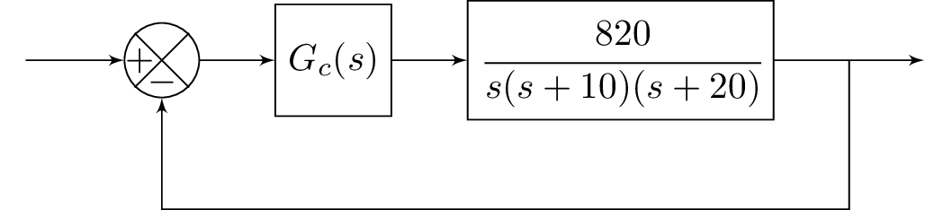
The code above generates a block diagram using the blox and tikz packages. The diagram consists of a feedback control system. It has one input labeled "A" and one output labeled "E". The signal "A" is connected to a block labeled "B" via a line without any text. Block "B" is a summing junction, represented by the command \bXComp, which adds the input signal to a feedback signal that is not shown. Block "B" is connected to a block labeled "C" with the transfer function , represented by the command \bXBloc[2]{C}{$G_c(s)$}{B}. Block "C" is connected to a block labeled "D" with a transfer function of , represented by the command \bXBloc[2]{D}{$\cfrac{820}{s(s+10)(s+20)}$}{C}. Block "D" is connected to the output block "E" via a line labeled with $C(s)$, represented by the command \bXLink{D}{E}. Finally, there is a return line, represented by the command \bXReturn{D-E}{B}{}, that connects the output of block "D" to the summing junction "B".
Keywords
TikZ, blox, control system, feedback, transfer function.
Source Code
\documentclass{standalone}
\usepackage{amsmath}  % For math
\usepackage{amssymb}  % For more math

\usepackage{blox}
\usepackage{tikz}
\begin{document}
\begin{tikzpicture}
\bXInput{A}
\bXComp{B}{A}
%\bXLink[$R(s)$]{A}{B}
\bXLink{A}{B}
\bXBloc[2]{C}{$G_c(s)$}{B}
%\bXLink[$V_1$]{B}{C}
\bXLink{B}{C}
\bXBloc[2]{D}{$\cfrac{820}{s(s+10)(s+20)}$}{C}
\bXLink{C}{D}
\bXOutput[4]{E}{D}
%\bXLink[$C(s)$]{D}{E}
\bXLink{D}{E}
\bXReturn{D-E}{B}{}
%\node (Gc) at (3.25,-0.95) {$G_c(s)$};
%\node (Gs) at (5.375,-0.95) {$G(s)$};
\end{tikzpicture}

\end{document}