Description
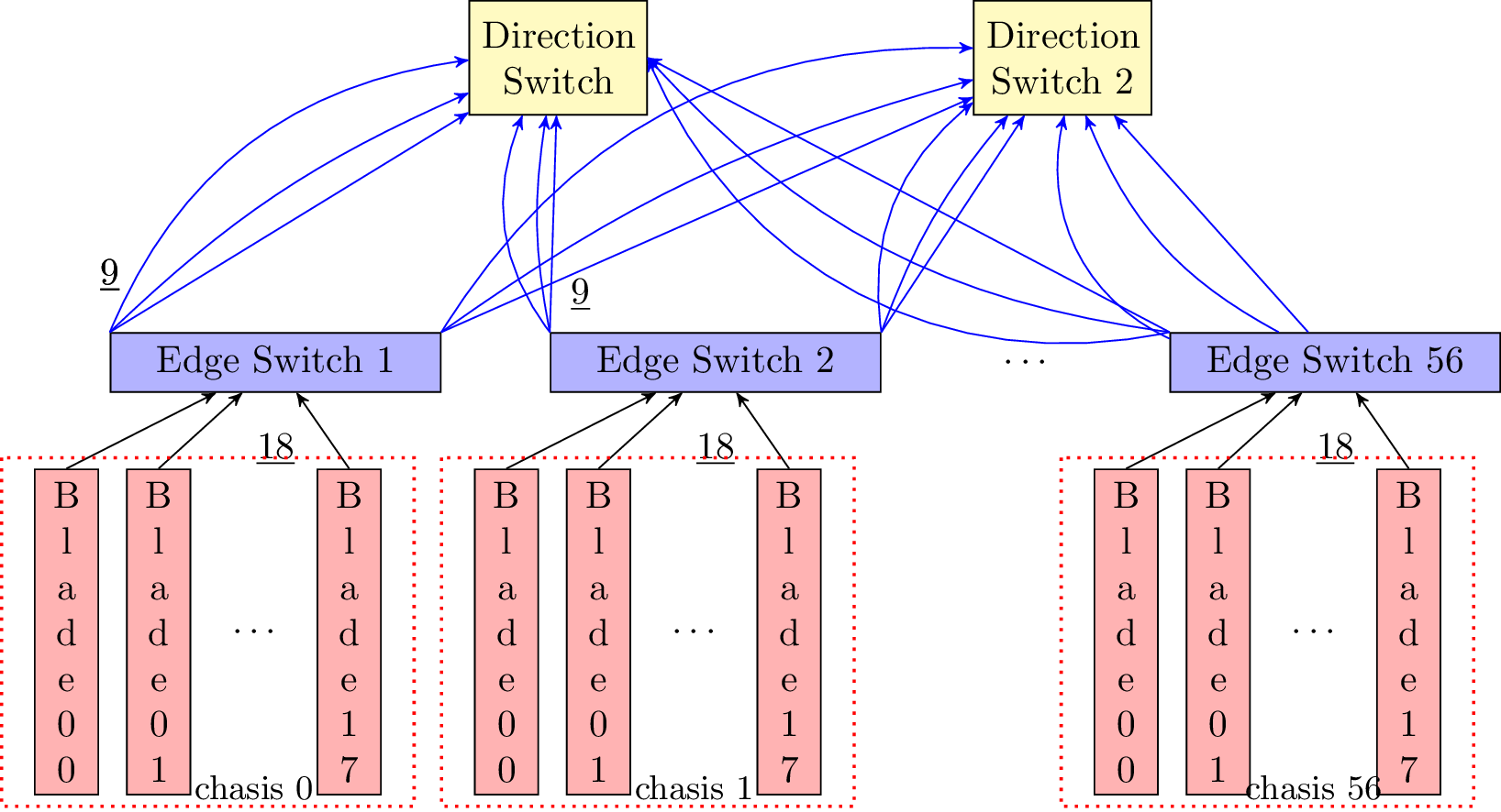
The code is a TikZ picture that creates a diagram of a network switch with multiple blades, edge switches, and direction switches. The switches are arranged in a hierarchy where the direction switches control the edge switches, which in turn control the blades.
The diagram consists of three sets of switches arranged horizontally using chains. The first set of switches are the two direction switches, labeled "Direction Switch" and "Direction Switch 2". The second set of switches are the edge switches, which are connected to the direction switches and labeled "Edge Switch 1" through "Edge Switch 56". The third set of switches are the blade switches, which are connected to the edge switches and labeled "Blade 00" through "Blade 17".
The blades are represented as vertical blocks labeled with their ID numbers. The edge switches are represented as horizontal blocks connected to the blades via arrows. The direction switches are not connected to the blades, but rather to the edge switches via chains. The diagram also includes a bounding box that encloses a set of blades and is labeled with the chassis number.
The styles for the switches are defined using \tikzset command. The edge switches are filled with blue, the blade switches are filled with red, and the direction switches are filled with yellow. The arrows are defined using the arrow style, and the boxes are positioned using the positioning library. The diagram also uses the calc library to position the bounding boxes.
Keywords
documentclass, usepackage, begin, tikzpicture, draw, node, edge, fill, circle, coordinate, right, left, below, above, rectangle, path, midway, label, end, center, tikz, style.
Source Code
\documentclass[tikz]{standalone}
\usetikzlibrary{arrows,chains,positioning,scopes,quotes,bending,calc}

\tikzset{
    edge/.style={draw,text width=8em,minimum height=1em,align=center,fill=blue!30},
    blade/.style={draw,text width=1em,minimum height=5em,align=center,fill=red!30},
    switch/.style={draw,text width=4em,minimum height=3em,align=center,fill=yellow!30},
    arrow/.style={->}
}

\begin{document}
    \begin{tikzpicture}[>=stealth']
    % Direction Switches
    {[start chain]
        \node[switch,on chain] (M0) {Direction Switch};
        \node[switch,on chain,right=3cm of M0] (M1) {Direction Switch 2};
    }
    % Edge switches
    {[start chain]
        \node[edge,on chain,below left=2cm and 0.25cm of M0] (N0) {Edge Switch 1};
        \node[edge,on chain,right=1cm of N0] (N1) {Edge Switch 2};
        %\node[block,on chain,join=by {arrow},right=1cm of N1] (N2) {N2};
        \node[on chain,right=1cm of N1] (N2) {$\cdots$};
        \node[edge,on chain,right=1cm of N2] (N3) {Edge Switch 56};
    }
    % Blade Switches
     {[start chain]
        \node[blade,on chain, below left=0.7cm and 0.1cm of N0] (B0) {B \\ l \\ a \\ d \\ e \\ 0 \\ 0};
        \node[blade,on chain,right=0.25cm of B0] (B1) {B \\ l \\ a \\ d \\ e \\ 0 \\ 1 };
        %\node[block,on chain,join=by {arrow},right=1cm of N1] (N2) {N2};
        \node[on chain,right=0.25cm of B1] (B2) {$\cdots$};
        \node[blade,on chain,right=0.25cm of B2] (B3) {B \\ l \\ a \\ d \\ e \\ 1 \\ 7};
    }
    % node containing number of blades
    \node[below =0.25cm of N0] (L1) {\underline{18}};
    % arrows from blade to edge
    \draw [->] (B0.north) -- (N0);
    \draw [->] (B1.north) -- (N0);
    \draw [->] (B3.north) -- (N0);
    \draw[red,thick,dotted] ($(B0.north west)+(-0.3,0.1)$)  rectangle ($(B3.south east)+(0.3,-0.1)$);
    \node [below = 1cm of B2](Lsd0) {\small{chasis 0}};
    {[start chain]
        \node[blade,on chain, below left=0.7cm and 0.1cm of N1] (C0) {B \\ l \\ a \\ d \\ e \\  0 \\ 0 };
        \node[blade,on chain,right=0.25cm of C0] (C1) {B \\ l \\ a \\ d \\ e \\ 0 \\ 1 };
        %\node[block,on chain,join=by {arrow},right=1cm of N1] (N2) {N2};
        \node[on chain,right=0.25cm of C1] (C2) {$\cdots$};
        \node[blade,on chain,right=0.25cm of C2] (C3) {B \\ l \\ a \\ d \\ e \\ 1 \\ 7};
    }
    % node containing number of blades
    \node[below =0.25cm of N1] (L2) {\underline{18}};
    % arrows from blade to edge
    \draw [->] (C0.north) -- (N1);
    \draw [->] (C1.north) -- (N1);
    \draw [->] (C3.north) -- (N1);
    % bounding box
    \draw[red,thick,dotted] ($(C0.north west)+(-0.3,0.1)$)  rectangle ($(C3.south east)+(0.3,-0.1)$);
    \node [below = 1cm of C2](Lsd1) {\small{chasis 1}};
    {[start chain]
        \node[blade,on chain, below left=0.7cm and 0.1cm of N3] (D0) {B \\ l \\ a \\ d \\ e \\ 0 \\ 0};
        \node[blade,on chain,right=0.25cm of D0] (D1) {B \\ l \\ a \\ d \\ e \\ 0 \\ 1 };
        %\node[block,on chain,join=by {arrow},right=1cm of N1] (N2) {N2};
        \node[on chain,right=0.25cm of D1] (D2) {$\cdots$};
        \node[blade,on chain,right=0.25cm of D2] (D3) {B \\ l \\ a \\ d \\ e \\ 1 \\ 7};
    }
    % node containing number of blades
    \node[below =0.25cm of N3] (L3) {\underline{18}};
    % arrows from blade to edge
    \draw [->] (D0.north) -- (N3);
    \draw [->] (D1.north) -- (N3);
    \draw [->] (D3.north) -- (N3);
        % bounding box
    \draw[red,thick,dotted] ($(D0.north west)+(-0.3,0.1)$)  rectangle ($(D3.south east)+(0.3,-0.1)$);
    \node [below = 1cm of D2](Lsd3) {\small{chasis 56}};

    % Edge switchs to direction switches arrows
    \path (N1.north west) edge[blue,->,bend left=10] node [left] {} (M0);
    \path (N1.north west) edge[blue,->,bend left=30] node [left] {} (M0);
    \path (N1.north west) edge[blue,->] node [left] {} (M0);

    \path (N1.north east) edge[blue,->,bend left=10] node [left] {} (M1);
    \path (N1.north east) edge[blue,->,bend left=30] node [left] {} (M1);
    \path (N1.north east) edge[blue,->] node [left] {} (M1);

    % N1, switch 2
    \path (N0.north west) edge[blue,->,bend left=10] node [left] {} (M0);
    \path (N0.north west) edge[blue,->,bend left=30] node [left] {} (M0);
    \path (N0.north west) edge[blue,->] node [left] {} (M0);

    \path (N0.north east) edge[blue,->,bend left=10] node [left] {} (M1);
    \path (N0.north east) edge[blue,->,bend left=30] node [left] {} (M1);
    \path (N0.north east) edge[blue,->] node [left] {} (M1);
    % N3, edge switch 56
    \path (N3.north west) edge[blue,->,bend left=20] node [left] {} (M0.east);
    \path (N3.north west) edge[blue,->,bend left=40] node [left] {} (M0.east);
    \path (N3.north west) edge[blue,->] node [left] {} (M0.east);
    \path (N3) edge[blue,->,bend left=20] node [left] {} (M1);
    \path (N3) edge[blue,->,bend left=40] node [left] {} (M1);
    \path (N3) edge[blue,->] node [left] {} (M1);

    \node[above right =0.10cm of N1.north west] (NL1) {\underline{9}};
    \node[above =0.25cm of N0.north west] (NL0) {\underline{9}};
    \node[above =0.25cm of N0.north west] (NL0) {\underline{9}};
    \end{tikzpicture}
\end{document}