Description
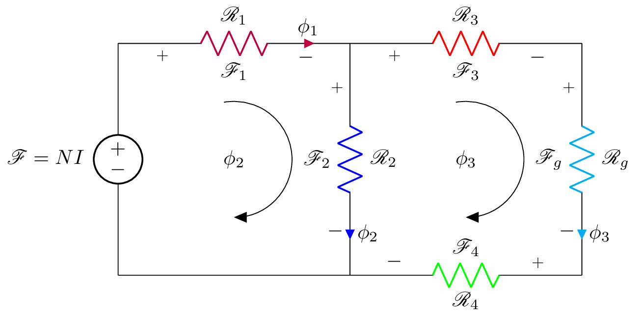
This is a LaTeX code that generates an electrical circuit diagram using the circuitikz package. The circuit has three resistors (R_1, R_2, and R_3) connected in series between a voltage source (F = NI) and a ground point. Another resistor R_4 is also connected in parallel to R_2 and both are connected to the ground point. There are three labeled currents phi_1, phi_2, and phi_3 that flow through the resistors R_1, R_2, and R_g respectively. The voltage drops across the resistors are labeled with F_1, F_2, F_3, and F_4. The diagram also includes arrows depicting the direction of currents in R_2 and R_g and labels phi_2 and phi_3 at their respective points. The code also uses several additional LaTeX packages for formatting and math symbols.
Keywords
circuitikz, graphicx, mathrsfs, latexsym, amssymb, amsmath, node, triangle, arc, to, V, R.
Source Code
\documentclass{standalone}
\usepackage[american]{circuitikz}
\usepackage{graphicx}
\usepackage{mathrsfs}
\usepackage{latexsym,amssymb,amsmath}
\newcommand{\equal}{=}
\begin{document}
	\begin{circuitikz}
		\draw (0,4) to [V,l_=$\mathscr{F}\equal NI$] (0,0)
		(0,4) to  [R,i>=$\phi_1$, l^= $\mathscr{R}_{1}$,v_>=$\mathscr{F}_1$, color=purple] (4,4)
	    (4,0) -- (0,0)
	     (4,4) to [R,i^>=$\phi_2$, l^= $\mathscr{R}_{2}$,v_>=$\mathscr{F}_2$, color=blue] (4,0)
		(4,4) to [R,l^= $\mathscr{R}_{3}$,v_>=$\mathscr{F}_3$, color=red] (8,4)
		(8,4) to [R,i^>=$\phi_3$, l^= $\mathscr{R}_{g}$,v_>=$\mathscr{F}_g$, color=cyan] (8,0)
		(8,0) to [R, l^= $\mathscr{R}_{4}$,v_>=$\mathscr{F}_4$, color=green] (4,0);
		\draw[thin, <-, >=triangle 45] (6,2) node{$\phi_3$}   ++(-90:1) arc (-90:100:1);
		\draw[thin, <-, >=triangle 45] (2,2) node{$\phi_2$}   ++(-90:1) arc (-90:100:1);
%		\node (phi) at (4.25,0.5) {$\phi_2$};
%		\draw[-stealth]  (4.25,2.5) to [bend left=90] (phi);
	\end{circuitikz}
	\label{fig:q1fig}
\end{document}