Description
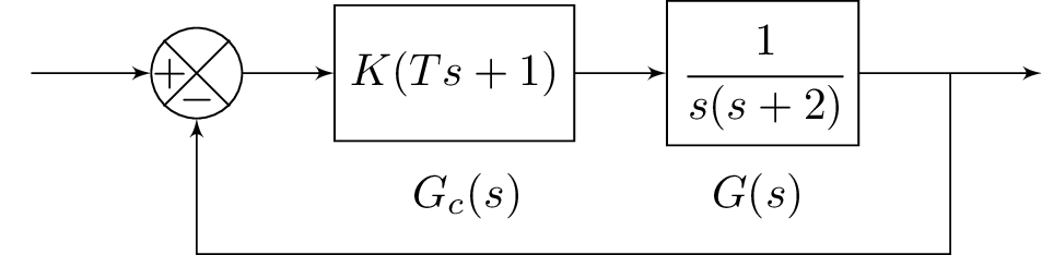
The code above produces a block diagram using the blox package in LaTeX. The block diagram consists of several components such as input, comparator, gain block, transfer function block, output, and a feedback loop. The nodes are labeled with letters such as A, B, C, D, and E. The package tikz is also used for drawing and positioning the nodes. Finally, two labels are added at the bottom for the controller transfer function Gc(s) and the plant transfer function G(s).
Keywords
standalone, amsmath, amssymb, blox, tikz, picture, block diagram
Source Code
\documentclass{standalone}
\usepackage{amsmath}  % For math
\usepackage{amssymb}  % For more math

\usepackage{blox}
\usepackage{tikz}
\begin{document}
\begin{tikzpicture}
\bXInput{A}
\bXComp{B}{A}
%\bXLink[$R(s)$]{A}{B}
\bXLink{A}{B}
\bXBloc[2]{C}{$K(Ts+1)$}{B}
%\bXLink[$V_1$]{B}{C}
\bXLink{B}{C}
\bXBloc[2]{D}{$\cfrac{1}{s(s+2)}$}{C}
\bXLink{C}{D}
\bXOutput[4]{E}{D}
%\bXLink[$C(s)$]{D}{E}
\bXLink{D}{E}
\bXReturn{D-E}{B}{}
\node (Gc) at (3.5,-0.95) {$G_c(s)$};
\node (Gs) at (5.75,-0.95) {$G(s)$};
\end{tikzpicture}

\end{document}