Description
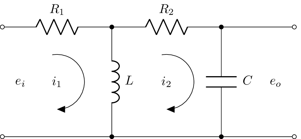
The code above is a LaTeX document that uses several packages, including circuitikz for drawing circuit diagrams, graphicx for including images, and mathrsfs for using a script font in math mode. The document defines a custom command \equal that produces an equals sign. It then creates a circuit diagram using circuitikz that consists of four components (two resistors, one capacitor, and one inductor) connected in a series with an input voltage source and an output voltage source. The circuit diagram also includes arrows indicating the direction of current flow in the circuit. The document also includes commented-out code for another circuit diagram.
Keywords
latexmk, pdfLaTeX, circuitikz, graphicx, mathrsfs, latexsym, amssymb, amsmath.
Source Code
\documentclass{standalone}
\usepackage[american]{circuitikz}
\usepackage{graphicx}
\usepackage{mathrsfs}
\usepackage{latexsym,amssymb,amsmath}
\newcommand{\equal}{=}
\begin{document}
		\begin{circuitikz}
		%\draw (0,4) to [open,v^>=$v_1(t)$,o-o]  (0,0) -- Open Short
		\draw (0,3) to [open,l=$e_i$,o-o]  (0,0) % input
			(0,3) to  [R, l^= $R_1$,-*] (3,3)	%R1
			(3,3) to  [L, l^= $L$,-*] (3,0)	%C1
			(3,3) to [R, l^= $R_2$,-* ] (6,3)	%R2
			(6,3) to  [C, l^= $C$,-*] (6,0)	%C2
			(8,3) to [open,l_=$e_o$,o-o]  (8,0) 	% output
			(0,0) -- (8,0) % wire in bottom
			(6,3) -- (8,3) % wire to output
			;

		% Current flows in tikz
		\draw[thin, <-, >=triangle 45] (1.5,1.5) node{$i_1$}   ++(-90:0.75) arc (-90:100:0.75);
		\draw[thin, <-, >=triangle 45] (4.5,1.5) node{$i_2$}   ++(-90:0.75) arc (-90:100:0.75);
%		\node (phi) at (4.25,0.5) {$i_2$};
%		\draw[-stealth]  (4.25,2.5) to [bend left=90] (phi);
	\end{circuitikz}
%	\begin{circuitikz}
%		%\draw (0,4) to [open,v^>=$v_1(t)$,o-o]  (0,0) -- Open Short
%		\draw (0,4) to [open,l^=$e_1$,o-o]  (0,0)
%		(0,4) to  [R,i>=$\phi_1$, l^= $\mathscr{R}_{1}$,v_>=$\mathscr{F}_1$, color=purple] (4,4)
%	    (4,0) -- (0,0)
%	     (4,4) to [R,i^>=$\phi_2$, l^= $\mathscr{R}_{2}$,v_>=$\mathscr{F}_2$, color=blue] (4,0)
%		(4,4) to [R,l^= $\mathscr{R}_{3}$,v_>=$\mathscr{F}_3$, color=red] (8,4)
%		(8,4) to [R,i^>=$\phi_3$, l^= $\mathscr{R}_{g}$,v_>=$\mathscr{F}_g$, color=cyan] (8,0)
%		(8,0) to [R, l^= $\mathscr{R}_{4}$,v_>=$\mathscr{F}_4$, color=green] (4,0);
%		\draw[thin, <-, >=triangle 45] (6,2) node{$\phi_3$}   ++(-90:1) arc (-90:100:1);
%		\draw[thin, <-, >=triangle 45] (2,2) node{$\phi_2$}   ++(-90:1) arc (-90:100:1);
%%		\node (phi) at (4.25,0.5) {$\phi_2$};
%%		\draw[-stealth]  (4.25,2.5) to [bend left=90] (phi);
%	\end{circuitikz}
	\label{fig:q1fig}
\end{document}