Description
The code above is a LaTeX document that defines a TikZ picture environment that generates a block diagram. The diagram consists of several blocks connected by lines and arrows, representing a control system with a feedback loop. The document uses the following packages: blox for creating block diagrams, tikz for drawing the diagram, and amsmath for mathematical symbols.
Within the tikzpicture environment, the blocks are created using the \bXInput, \bXComp, \bXBlocr, and \bXOutput commands from the blox package. The blocks are connected using \bXLink and \bXLinkxy commands, and a feedback loop is created using the \bXReturn command (which is commented out in the code).
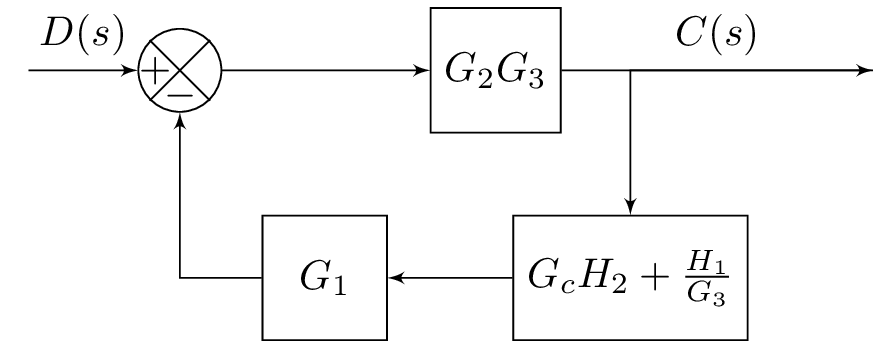
The diagram consists of the following blocks, in order from left to right:
- Input block labeled "A"
- G2G3 block with transfer function
- Output block labeled "E"
- GcBlock block with transfer function
- G1 block with transfer function
- Comparison block labeled "B"
The diagram also includes two branches: one from the output block to a point labeled "returnDown", and one from the GcBlock to the G1 block.
Keywords
standalone, blox, tikz, amsmath, positioning.
Source Code
\documentclass{standalone}

\usepackage{blox}
\usepackage{tikz}
\usepackage{amsmath}  % For math
\usetikzlibrary{positioning}
\newcommand{\equal}{=}
\usepackage{tikz}


\begin{document}

\begin{tikzpicture}
\bXInput{A}
\bXComp{B}{A}
\bXLink[$D(s)$]{A}{B}
\bXChain[5]{B}%
{G2G3/$G_2G_3$}
\bXOutput[7.5]{E}{G2G3}
\bXLink[$C(s)$]{G2G3}{E}
\bXBranchy[5]{E}{returnDown}

% return loop
\bXBlocr[3]{GcBlock}{$G_cH_2+\frac{H_1}{G_3}$}{returnDown}
\bXBlocr[3]{G1}{$G_1$}{GcBlock}
\bXLink{GcBlock}{G1}
\bXLinkxy{G1}{B}
\bXLinkxy{E}{GcBlock}
%\bXReturn{G3-E}{B}{}
\end{tikzpicture}

\end{document}