Description
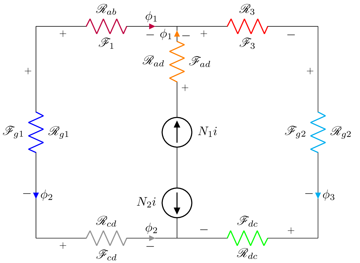
This is a LaTeX code that generates an electrical circuit diagram using the circuitikz package. The diagram represents a transformer-coupled amplifier, with various resistors and sources. The circuit consists of three resistors and three sources, two of which are current sources. The circuit also includes two transformers with a ratio of N1:N2. Each resistor and source is labeled with a symbol that indicates its name, current or voltage direction, resistance, and/or voltage. The colors of the resistors and sources are specified using color names. The mathrsfs, latexsym, amssymb, and amsmath packages are used to typeset the mathematical symbols and characters. The document class is set to standalone, which is used to generate a single image file of the circuit diagram.
Keywords
circuit, tikz, resistor, inductor, voltage, current, color, gray, purple, orange, red, blue, green, math, subscript, label.
Source Code
\documentclass{standalone}
\usepackage[american]{circuitikz}
\usepackage{graphicx}
\usepackage{mathrsfs}
\usepackage{latexsym,amssymb,amsmath}
\newcommand{\equal}{=}
\begin{document}
	\begin{circuitikz}
		\draw (0,6) to [R,i^>=$\phi_2$, l^= $\mathscr{R}_{g1}$,v_>=$\mathscr{F}_{g1}$, color=blue] (0,0)
		(0,6) to  [R,i>=$\phi_1$, l^= $\mathscr{R}_{ab}$,v_>=$\mathscr{F}_1$, color=purple] (4,6)
	    (0,0) to [R,i^>=$\phi_2$, l^= $\mathscr{R}_{cd}$,v_>=$\mathscr{F}_{cd}$, color=gray] (4,0)
	    (4,2) to [I,l_=$N_1i$] (4,4)
	    (4,2) to [I,l_=$N_2i$] (4,0)
	    (4,4)  to  [R,i>=$\phi_1$, l^= $\mathscr{R}_{ad}$,v_>=$\mathscr{F}_{ad}$, color=orange] (4,6)
		(4,6) to [R,l^= $\mathscr{R}_{3}$,v_>=$\mathscr{F}_3$, color=red] (8,6)
		(8,6) to [R,i^>=$\phi_3$, l^= $\mathscr{R}_{g2}$,v_>=$\mathscr{F}_{g2}$, color=cyan] (8,0)
		(8,0) to [R, l^= $\mathscr{R}_{dc}$,v_>=$\mathscr{F}_{dc}$, color=green] (4,0);
	\end{circuitikz}
	\label{fig:q1fig}
\end{document}